


Dot Matrix LED Display, Chain Kit, Max7219 [Set]


$3.00 – $4.40
- Description
- Additional information
- Reviews (21)
- Product Enquiry
Description
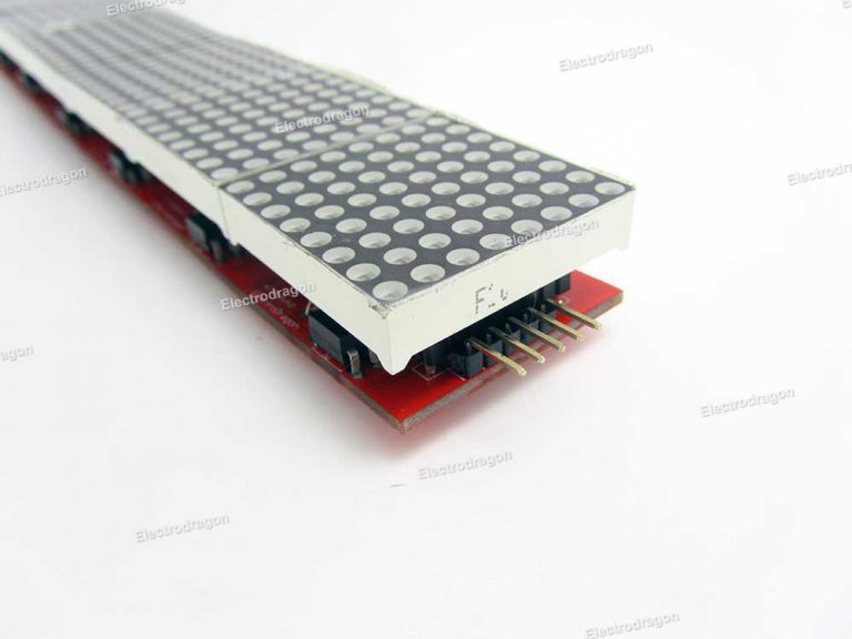
- RA modularized LED matrix display, you can connect as much as you can to make a big sliding display.
- Easy to assemble and connect in a flexible way.
- Supported by arduino library called “parola” as we know, this is also a hardware redesign, and there should be more available demo code you can find on internet or develop yourself.
- A kit includes all the parts in the main image, and this is the price for one kit.
- When you connect more than 12 modules in one chain, you should concern provide a external high current power instead of the power from arduino, since the arduino can hardly afford this anymore.
- Module size 3.2 * 3.2 CM
Update:
- From 2016-12-08, this changed to 2 sets or 3 sets, the PCB are pre connected, no need to soldering the pins and add jumper in the between, save a lot of work, elimiate error, and much better physical strength.
- You can make 2 set or 3 set directly, or any combination like 2+3, 3+3 chained.
- Add a few glue on the few jumpers will make the chained display perfectly fixed.
Package includes:
- 2 or 3 pcs Boards presoldered SMD parts, 2 or 3 pcs 3mm dia. dot matrix display
- 2pcs 1x5pin 0.1” pin header (chain connection)
- 2 or 3 pcs 1x8pin 0.1” pin header (optionally for dot matrix socket)
- 1pcs bended 1×5 0.1”pin header (for wiring)
- 5 jumpers (chain connection)


koursaros (verified owner) –
Very nice kit with all needed
Check Chow’s video on how to make it a chain.
Good price as always.
kblnz (verified owner) –
Great kit, all required items and PCB same size as matrix for easy alignment
Chao (store manager) –
Hello Charles,
Fixed the project link, it should be a simple projects, and supports also other MAX7219 arduino libraries too, you need try.
Boards has no different with any others, we just shrink the size a little bit.
Charles Morgan (verified owner) –
Figured it out, China right…. plugged in on the right side…..
improvements need to be made is box or line for LED matrix orientation.
You will need the following software libraries.
Library for Max72XX LED Matrix Display v2.4
http://arduinocode.codeplex.com/releases/view/120493
KeySwitch digital input (small) library
http://arduinocode.codeplex.com/releases/view/119934
Parola for Arduino
http://parola.codeplex.com/
Please remove my one star review.
Chao (store manager) –
Yes,
Indeed plug on the right side, DI stand for Data input, that is not very clear indeed.
Parola should be the simple one to use, easy to make it works.
Thanks!
Charles Morgan (verified owner) –
I would also say, for that library, I don’t recommend anything less than 8 kits unless your advance coder. I keep getting over lap artifacts dues to the lack of two modules.
I had one kit with Yellow headers, the next 5 had the Black headers. I’ll admit I actually liked the yellow headers. but all seems well I’ll drop another order here shortly for 3 more kits.
Thanks!
Docedison (verified owner) –
I’ve used the v2 Boards and I have few problems related to artifacting… with the OLD libraries. The libraries have been rewritten to fix the artifacting… it was a timing issue and a buffer modification… I just bought 16 more from ElectroDragon because they are a very nice “Mountable” PCB… unlike the “Ebay” pretenders… (junk dealers with second class “Stuff”).
Buy the best here… leave the junk for the rest…
Doc
kimhochreiter –
Excellent site functionality and organisation. Thanks very much
jpoilux (verified owner) –
have 2 kit, so good 🙂
Thank you ElectroDragon !
Charles Morgan (verified owner) –
Bought three kits a while back, put them together tonight, all three were missing the header pins for thew jumpers.
Chao (store manager) –
Hello Charles,
Sorry, indeed we have few these kits missed the pins, have fixed the problem on stock, if you need these pins please let me know via email, thank you!
stevekamo (verified owner) –
I bought 20 kits. Excellent quality. Quick shipping. Thanks!
john.witherspoon (verified owner) –
just received 10 kits – assembled one and confirmed that the jumpers do limit full insertion of the matrix onto the board. Has anyone tried installing the header pins and jumpers on the back of the boards instead of the front?
Joakim (verified owner) –
Just bought 22, soldered it up and it works GREAT! Gonna by 58 more now 😀
Seriously, I can only recommend this!
john.witherspoon (verified owner) –
I confirm that these are excellent kits. I bought 10 to try them and now have returned and purchased 16 more. The circuit boards are of high quality, packaging of components was complete and shipping only took about 7 days to Toronto. Assembly is straight forward. I tried installing the jumper headers both on the front and back of the boards. While both configurations work, I prefer having backside headers as this enables full insertion of the matrix pins into the board, although mounting requires standoffs. I am using 1/2″ standoffs resulting in a total depth of 1.0″.
Teachdude (verified owner) –
I wanted to submit a possible solution to the problem of the excessive header height interfering with the display being flush with the board. This my solution to the problem: 1) Solder the header pins (both sides) to the top of the board like normal. 2) Take a sharp knife and pry up (remove) the yellow plastic separator that holds the header pins. 3) Slide the jumpers on header pins. The pins will now stick up above the jumpers. 4) Trim the pins sticking up with diagonal-cutters. Now when you join the circuit boards together with the jumpers, there will be enough room for the displays and the header pins not to interfere with each other.
This solution has worked very well for me.
mathias.wilhelm (verified owner) –
Salut,
I ordered 4, received 3 due to package error and a refund within 24 hours – order 9 more now as this is good service!
I soldered the connecting pins pointing to the back so they are completely out of the way and had no issues at all with this setup to align the modules. I also ran the module using a chipKit board (HelvePic32) without any issues using oth 3.3V and 5V as supply voltage. I have not yet tested the parola library as it uses AVR interrupt handling which I need to change to the much easier chipKit interrupts. If there is an interest, I will post the updated code
Ciao, Mathias
John Ang –
Does the LED come in other colors like green, blue, orange or white
Chao (store manager) –
Sorry, nope, other color is difficult for us to arrange it now.
Jorge Peralta –
I really like this kit, even though it takes a lot of figuring out.
a) There is no silkscreen on the board, indicating pin names or IN/OUT direction. Had to deduce it by carefully looking at photos and experimenting. The boards shown in the ad show pin names, the ones that I received are missing all markings.
b) There is no indication of which direction the LED array should use to be mounted on the board, so there is a 50-50 chance of getting the first one wrong.
Just make sure you get one chip / array working by itself (you don’t need to separate the boards), so that you can figure cabling and array orientation before to go soldering a mess of these up.
If you are using more than five modules, you should really use a separate 5V feed to the array, since the arduino can’t supply enough
current to be reliable under heavy load.
You can solder ‘U’ shaped pieces of wire into the interconnecting pins if you don’t want to use jumpers.
jandp.fitch (verified owner) –
I suggest the Dot Matrix Chain Display Kit, Max7219, Parola [Set] could be improved by perforating the boundary of the boards so they can be snapped apart for single boards. Then you only need to make 3/5/10 modules together as they can be snapped off as needed.