


![0.96'' 128*64 OLED Display Blue [IIC, SPI] - Image 1](https://www.electrodragon.com/wp-content/uploads/2015/11/096-OLEDs-560x560.jpg)
![0.96'' 128*64 OLED Display Blue [IIC, SPI] - Image 2](https://www.electrodragon.com/wp-content/uploads/2014/12/0.96-12864-OLED-Display-IICSPI-01-400x400.jpg)
![0.96'' 128*64 OLED Display Blue [IIC, SPI] - Image 3](https://www.electrodragon.com/wp-content/uploads/2014/12/0.96-12864-OLED-Display-IICSPI-02-560x560.jpg)
![0.96'' 128*64 OLED Display Blue [IIC, SPI] - Image 4](https://www.electrodragon.com/wp-content/uploads/2014/12/0.96-12864-OLED-Display-IICSPI-04-400x400.jpg)
![0.96'' 128*64 OLED Display Blue [IIC, SPI] - Image 5](https://www.electrodragon.com/wp-content/uploads/2014/12/0.96-oled-400x400.jpg)
![0.96'' 128*64 OLED Display Blue [IIC, SPI] - Image 6](https://www.electrodragon.com/wp-content/uploads/2014/12/0.96-oled-02-400x400.jpg)
- Description
- Additional information
- Reviews (14)
- Enquiry2
Description
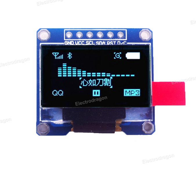
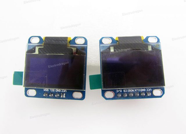
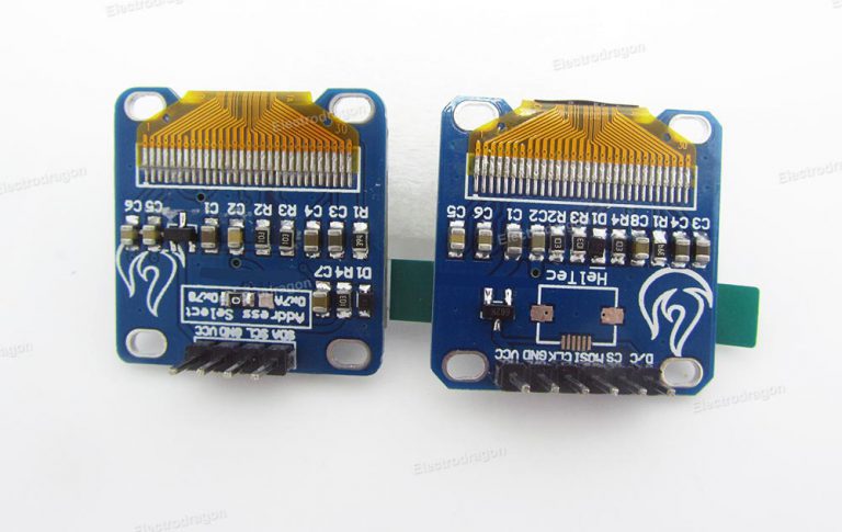
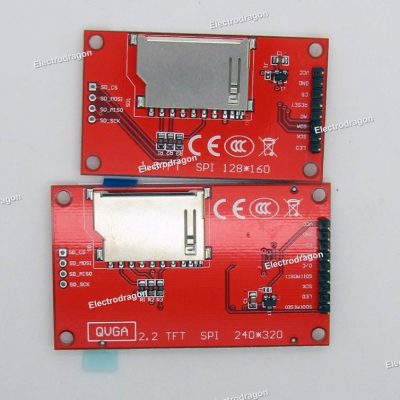
A new small size OLED, display on 128*64, and two types of interface IIC and SPI (on two different boards).
Features:
- Drive IC is SSD1306, easy to find arduino library for it.
- Wide input voltage: 2.5V-5.5V
- Wide display agnle 160 degree.
- Super low power consumption only 0.06W on regular display, not TFT display can compare.
- Industrial level temperature: -30~70 degree.
- Board size: 29.3*27.1 mm
- Application: design for size, quality and power consumption oriented products: smart watch, portable industrial, medical devices, special headset, player, etc


![EDS TFT LCD Display LCM, SPI SD-Card Touch, 1.8~4.0'' [Size]](https://www.electrodragon.com/wp-content/uploads/2013/10/EDS-2.4-TFT-LCD-02-560x560.jpg)


![[chip-hold]MCP23017 IIC to 16CH GPIO Expander Board](https://www.electrodragon.com/wp-content/uploads/2019/10/MCP23017-IIC-to-16CH-GPIO-Expander-01-560x560.jpg)


Harry (verified owner) –
This is a must for all your small projects. This display is super bright and crisp. Much better than TFT and LCD. Although it’s not a very large display, it’s more than enough to show you things like temperature, humidity and so on. Power consumption is very low. You can shut it down and power it up in your Arduino sketch. Works very well with the Adafruit Library.
Bajdi (verified owner) –
Bought the I2C and SPI version and tried them out with the Arduino Adafruit & u8g library. Both libraries work perfectly with the I2C and SPI OLEDs. The SPI version is a bit faster then the I2C one. Really happy with these small displays.
My video of both displays in action: https://www.youtube.com/watch?v=S5-4Lap7fzQ
rudi (verified owner) –
Hi Guys
i get my OLED today.
i will inform:
my SPI OLED was printed: GND, VCC, SCL, SDA, RST, D/C
no problem 😉
i connect this:
GND = GND
VCC = VCC
SCL = CLK
SDA = MOSI
RST = RST
D/C = D/C
the cs is allready connected to GND at OLED Board.
This works like a charme in arduino IDE,
DIGI Pins are:
GND = GND
VCC = VCC
10 – SCL = CLK
09 – SDA = MOSI
13 – RST = RST
11 – D/C = D/C
i used for test
Adafruit_GFX.h
Adafruit_SSD1306.h
if you need a Arduino Sketch – i will upload over email to my friend chao 😉
best wishes to you guys!
and – if we not hear again:
Happy Spring Festival to you!!!
best wishes
rudi 😉
telefonni (verified owner) –
Bright and easy readable. Wide angle. Very useful.
nfriedly (verified owner) –
I also tried out both the I2C and SPI editions and I’m verry happy with both. I found the I2C version to be a bit of trouble at first, but mainly because the address is 0x3c while the back of the board appears to indicate that it’s either 0x71 or 0x78.
Also, the SSD1306 library link is broken, but if you change the subdomain to www, then it works: https://www.electrodragon.com/wp-content/uploads/2012/01/SSD1306.zip
Christoph (verified owner) –
Really good display. A bit small but looks great! Perfect for applications where you need a small display with relatively high resolution.
jpmsparks (verified owner) –
I wanted to use the SPI version of this product with the 8266-12E. I am able to get it working with the 8266-!2E if the Wifi library is not used, and I can get the Wifi access point and station working without the SPI OLED, but I cannot get both working simultaneously. When I try to use both, the 8266-12E watchdog timer reboots the 8266-12E repeatedly. I am using GPIO 16 for RST, 14 for SCL, 13 for SDA, and 2 for DC connections.
I suspect an issue in the SSD1306 library. I am using
jpmsparks (verified owner) –
Got this SPI OLED to work with the ESP8266-12E while the Wifi connected to a router. I found the issue and will post it here in case anyone else runs into this. By default, the 8266 uses GPIO 2 for UART1 on the ESP8266, and this UART1 can only be used to send
data – many use this as a debug port is they are also using UART0 for other things (like talking to another component, which I was doing). The problem is that GPIO2 must be used for D/C functionality for the SPI OLED and apparently cannot be remapped (as I was trying to do for debug purposes) succesfully. Bottom line: hook up the SPI pins from the 8266 exactly as stated, do not try to use them for anything else.
mellamanjefe (verified owner) –
I have an older SPI version with the following pins: GND, VCC, SCL, SDA, RST, D/C. Wire it as rudi did with an Arduino and it should work.
When connecting to an ESP8266 the SPI wiring that worked for me is as follows:
POWER:
GND -> GND
VCC -> VCC
OLED ESP8266
SCL 14
SDA 13
RST 2
D/C 12
Good luck!
maguye007 (verified owner) –
Fantastic little modules! My (SPI) unit came labelled as GND, VCC, D0, D1, RES, DC and CS. D0 is actually SCK for SPI, and D1 is MOSI for SPI. That said, wire the modules up as described in the Wiki and use the Adafruit library. Works like a charm.
Tyrone (verified owner) –
Great display, works as expected. TIP: The address to this device is actually 0x3C
geraldhasmail (verified owner) –
Works great! A few different libraries to choose from on Arduino, and loads of applications!
porkyneal (verified owner) –
Great little displays, work perfectly.
vortex_123 (verified owner) –
The I2C model works very well ! Awesome!