


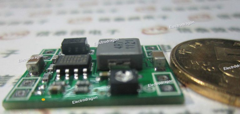
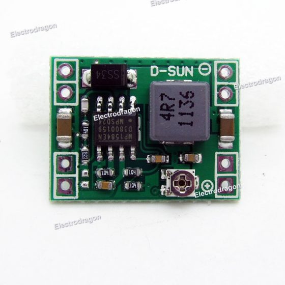

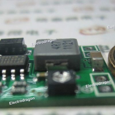
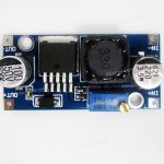
Tiny DC Buck ADJ Module 2A, MP1584EN
$0.70
- Description
- Additional information
- Reviews (13)
- Enquiry2
Description
Application: suitable for DIY portable battery, power supply for communication device, and any other cases that very restrict to the weight and size.
- Input Voltage: 4.5-28V
- Output Voltage: 0.8-20V
- Output Current: 3A (Max.)
- Output Voltage Ripple: <30mV
- Switch frequency: 1.5MHz(Highest),typical 1MHz
- Operational Temperature: -45℃~ +85℃
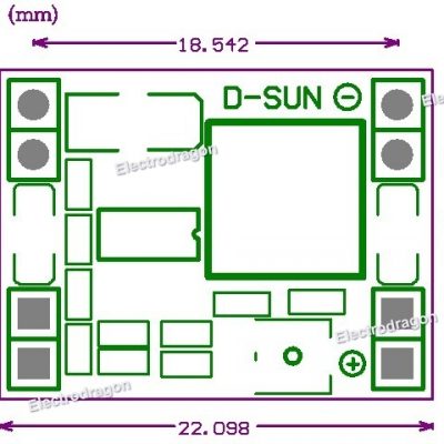
- Size: 22mm * 17mm * 4mm
Additional information
| Weight | 0.01 kg |
|---|


Bajdi –
Works better then the cheap LM2596 boards. Tried it with a 2A load and it stays cooler then the LM2596.
Foppe Hendrik (verified owner) –
Nice litle device. It was only after ordering it that I thought it would only step-down and not regulate the output voltage. But soon after delivery I connected it to a lab-voltage source and noticed that the output is very steady, as long as the input is slightly higher than the wanted output voltage.
I asked the Electrodragon staff a question about this module and even during their holiday they replied very quickly. Very nice service!
Bajdi (verified owner) –
I tested several voltage regulators including this one, results are on my blog : http://www.bajdi.com/testing-switch-mode-voltage-regulators/
Efficiency is very good.
Sandman333 (verified owner) –
I ordered two of these modules, and only one worked on arrival. After some quick troubleshooting, I determined that the inductor was not completely soldered on the other board. All I had to do was reheat the pad and inductor to fix it, so all is fine now.
Even considering the repair I had to do, this is still a great value. I will probably order a lot more of these next time, thanks!
donaldkamp (verified owner) –
Pretty cool. I had a little trouble at first. ‘Kept turning the pot anti-clockwise but it didn’t seem to reduce the voltage. Upon following the traces I realized that the potentiometer is set up to attenuate in the clockwise direction (Duh! My mind-lock prevented me from trying that). The pot has a flat spot while the wiper is at the opposite extreme. Looking at the photo, the wiper is at the 3 o’clock position which is about 10 volts. 6 o’clock is about 4.5 volts.
But this diversion got me wondering: What’s the failure mode if the wiper gets corroded and goes open circuit? Aha. We can test this ’cause the wiper doesn’t have stops. Crank it to the 9 o’clock position and it runs up on the ceramic and is out-of-circuit. You’ll find it jumps up to full voltage (20 volts). Not my favorite… But there is an easy fix. Just solder in a 120K-ohm resistor between the positive output connection and the potentiometer leg closest to the edge of the card. That will cut the output range in half. Nice!
medvonok (verified owner) –
Small, cheap and powerfull.
overdrive (verified owner) –
This is a very stable and solid regulator at a very good price point. highly recommended.
Christoph (verified owner) –
Just works! I have several of these in use and havent been disappointed so far. The output voltage is very stable.
overdrive (verified owner) –
Very nice and compact and works well. Well worth it
diazfjg (verified owner) –
It’s very nice and small factor dc converter.
vestale (verified owner) –
good quality
brandonw (verified owner) –
Excellent performance for the price. My only issue is with the potentiometer — it is too coarse for the 0.8 – 20V range of the module. I could not adjust to 3.3V and have it hold. Just removing the screwdriver from the pot would shift 100’s of millivolts. I consulted the MP1584EN datasheet to see how the output voltage is set. While inspecting the module to determine how the voltage divider was routed, I realized there is an populated resistor pad that is in parallel with the pot! Very nice, no hacks/bluwires needed! The formula in the datasheet led me to select a 68Kohm resistor to add to this unpopulated pad. Once I did that, I could very easily and reliably adjust the range from 0.8-5.8V.
I wager in the majority of cases people will want to step-down to 3.3V, 5V, or 12V. It might be better if this extra resistor was already populated for optimum 3.3V or 5V use, with instructions to remove it for full range up to 20V.
Chao (store manager) –
Hi, also have the fixed output version for buck order, if you need please contact us by email, thanks!