


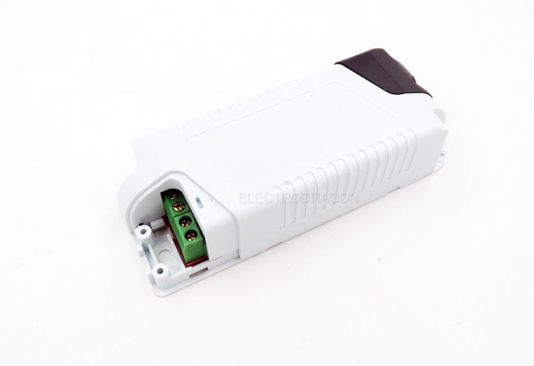
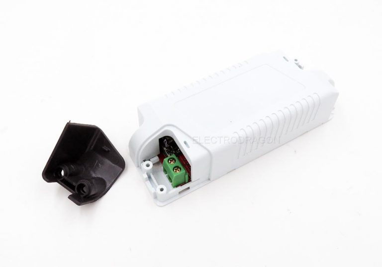


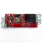
- Description
- Additional information
- Reviews (94)
- Enquiry2
Description
The purpose of this design is for learning how to play with the hardware and software of a IOT project, it is based on price competitive wifi module ESP8266.
Hardware Features:
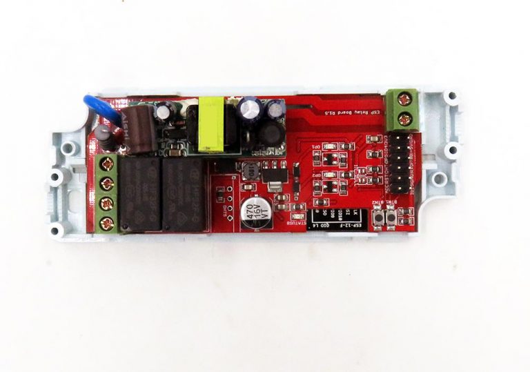
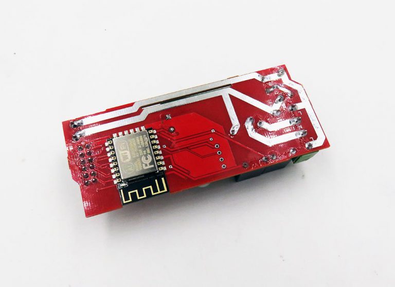
- Based on ESP-12F ESP8266 Wifi Module
- Case general dimension is 111*42 mm.
- Two Lead out buttons BTN1 and BTN2
- One status LED, indicating connecting status in demo code
- A few lead out pins, from top (left) to bottom (right):
- Resevered design for temperature sensor DHT22
- Screw terminal which are easy for wiring output.
ACDC Power Supply Features:
- High quality ACDC power modules EDP01
- Input volatge 85 – 265VAC, 0.8A 5V DC output
Relay And Control Features:
- This relay board use one AC input, and supports two relay AC output.
- Please note the output AC power comes/connected from/with input AC power. Relay only play as on/off switch for AC power. Will be danergerous to use in any other cases.
- Relay Specification HF32F-G-5-HS
- Common – open,
- 10A
- 250VAC or 30VDC
- Two relay indication LEDs
Package include:
- Main Board and lastic enclosure
- Not including screws for sample orders only 1pcs, but included for more than 1pcs. Please prepare M2*8 or M2.2*6, etc crews by yourself.
Additional information
| Weight | 0.07 kg |
|---|---|
| ESP |




![ESP8266 SMD Breakout Board R2 [version]](https://www.electrodragon.com/wp-content/uploads/2015/06/esp-smd-adapter-board-2.1-560x560.jpg)




rithvikpodduturi –
Awesome Product just two of them waiting for them to arrive….
Ed –
Great idea, great price! I’d also love to see a DC version of this with a buck converter in place of the AC power supply.
claude (verified owner) –
Hello, I have just received the board. I am very existed starting with it but I am lost now. Maybe you can help me. What I want to do it to send AT command to the board in order to trigger something through the relay. Could you explain again how I can do that, please.
I have plugged the board to the AC and I can see red led lighting supposing it will generate correct power.
The status red light is ligthing (not blinking).
There is an wifi access point available for sure.
Using Windows network manager software, I can see AI-THINKER.
I would like to see my ESP8266 connected to my current wifi access point in order my router assign ip address on my current network.
My understanding was I was able to that using ESP touch api on iphone but cannot access my current wifi access point (Esptouch fail).
Appreciate your help step by step please?
Tell me if I have to physically connect the ESP board to my computer?
regards thanks
Claude
Giuseppe Bonanno –
I loaded the board with a sketch of Souliss framework ( http://www.souliss.net ) that i use for automate my home, and it works perfectly.
At moment only comment is that the AC lines on the PCB are quite thin.
Chao (store manager) –
Hi Claude, you can try with the AT firmware of command AT+CIOWRITE=12,1, like this, see more info at https://www.electrodragon.com/w/ESP8266_AT_Commands.
But flash the firmware is pretty important to understand the proper way to use …
aviyahalom (verified owner) –
Received mine today. Still playing around with it. What does button 1 do? I know button 2 is to ground GPIO 0 and to allow flashing, but what is the 2nd button for?
One small issue. The GND pin is very close to the power convertor making it difficult to connect for flashing. I had to bend the pin to make the connection. An extra millimetre would have helped.
Ilan Klein (verified owner) –
the board itself looks OK, it has been discussed here, about the design and how it can be better, but the case is a bit problematic, it does not expose the outlets of the 2 relays, out of 4 green terminal, only 3 are accessible, would we be able to get a better case? also I would think that raised buttons would be good here, so that u can access them when the case is closed up.
Chao (store manager) –
Hello Llan, it is the most fit-able case we can find … it is a existed case in the market, not designed and made by ourselves, to fully access the terminals, you may need thinner wire cables, or drill/eliminate the installation screw bars.
Igor –
Thank you very much for everything!!!
This guys are awesome and they products also!!!
aviyahalom (verified owner) –
CAUTION: Electrodragon personnel, please correct me if I’m wrong, but there appears to be NO ISOLATION on this board, with the neutral (0) mains input connecting directly to the neutral (0) terminal of the relay outputs. (This effectively means there’s potentially high voltage AT BOTH ENDS OF THE BOARD – and it would be extremely unwise to use the relays for anything other than mains voltage.) I have revised my rating from 4 to only 1 star until someone convinces me otherwise.
Chao (store manager) –
Hi aviyahalom, Yes indeed, this is not clear since it is not mentioned in the product description, the output AC power comes from the input AC power, we want to make this is convenient to be. Sorry this is unclear and cause any problems for you, but our current version will be like so.
rick1 (verified owner) –
Awesome little devices, didn’t manage to get it to work with the built in firmware (too much Chinese), but I DID get a simpler firmware written using the aRest library and Arduino. Wrote a quick blog post here if anyone else is interested: http://refactor.tonoli.net/2016/05/09/dual-relay-control-over-wifi-for-6/
rick1 (verified owner) –
Unfortunately I’m adding a second review for the second board I got, it appears to be faulty, cannot access the ESP chip on it at all via the pins. I followed exactly the same process as the first board but I cannot flash it 🙁
How do I go about getting this replaced? I’d like to order more of these but cannot unless I can get this one replaced.
bapt1080 (verified owner) –
It was a good idea but unfortunately esp board reset during a change of state under 220v 🙁
big isolation problem
unusable board: – (((
Chao (store manager) –
Hi Bapt1080, tried with 220V and 110VAC, seems no problem here or can not represent your problem here, can you contact us to check, maybe any wrong steps on your setup? Thanks.
Baptiste (verified owner) –
edit : after very great communication with the seller, problem being resolved
thx
daryl (verified owner) –
Nice product – bought 2. I re-flashed with ESPEasy, added DHT22 and waterproof DS18B20. Connected to Domoitcz home automation system for my Aquarium lights & water/room temperature. Only problem is that when fluorescent light is turned ON/OFF on Relay 2 ESP8266 reboots. No problem with normal filament lamp.
– May need extra capacitor or filter on ESP8266 power. (AUS 240v)
redfoxy (verified owner) –
I bought 3 and 1 have troubles on GPIO12, you can’t use it just connecting it you must put a firmware and send lua files, for other it’s ok, I want more of them! 😀
ddos –
Good product, sharing shematic will be great. Better be micro usb serial converter on it. Relay 1 (gpio 12) is not working.
Miguel Angel Ajo (verified owner) –
The board works, but, sometimes it freezes when you drive load ON/OFF the 220V circuit. For example, try something with 800W, eventually the ESP-12 freezes. That indicates an isolation issue. I’m experimenting with bigger capacitors near the relays, near the esp module, and at the 3.3V regulator input. Probably a choke before the ESP would alleviate any possible spikes due to switching noise.
Also the 220V tracks should be wider.
Chao (store manager) –
Hello Miguel, Yes, it has little chance to cause this problem happen when switch on/off often,we didn’t clearly find this during designing it. But we have solved the two issues as you mentioned in a new updated version, will be done and produce in next week. We will contact you by email for this. Thanks.
Otuk –
I bought 2 of these and would like to use Arduino IDE/c instead of at commands, is there a post or blog about how to do this?
Quentin Lindh (verified owner) –
I am experiencing the same reset of esp board when I switch a load off. (small electric fan .2 amps).
Chao, you mention a board version that fixes this issue, is this the version that is in stock now?
Is this noise on the RST pin as discussed in this post?
http://www.esp8266.com/viewtopic.php?f=13&t=1924&start=60
Is there a known rework solution?
Chao (store manager) –
Hi Quentin, R1.1 is the updated version, nearly have no problem of this anymore, compare to old version, switching more than hundreds times should have no problem. It is not a problem of RST, RST does not connect to anything as suggested. It is a problem of power supply and also maybe isolation, this should be fixed now. We will contact you in details for this.
nuno –
I will buy one to test. I need it to trigger blinds windows. But i know nothing how to programe it even with good programmer skills. Hope i see where i can start and copy code to learn
Otuk –
I started a blog on use of this and will publish code as well: It will talk about how to use Arduino IDE to use this board.
http://blog.kodeten.com/experimenting-with-a-new-gadget-electrodragons-relay-board/
Øyvind –
I tried contacting support to get a clear answer as to how much power this is rated for, but have yet to receive an answer. The traces look far too thin to handle 10A.
Chao (store manager) –
Not yet run test for it so don’t know, only can tell a rough calculation, but indeed thin trace for pass large current.
oversc0re (verified owner) –
It’s an awesome board for $6, but it has some flaws that could be easily corrected:
– As already stated AC PCB traces are too thin for 10A!
– There could be jumpers to disconnect relays from mains for DC applications
– It would be great to have RST pin connected to connector for easier flashing.
Khan –
hi there,
I believe issue with freezing also has to do with EMI at load side when using with inductive loads. Anyone tested load with MOV (Varistor) at load side for surge protection?
thanks
Quentin Lindh (verified owner) –
Electrodragon shipped me v1.1 boards which resolved the issue that I had with resets on the 1.0 and they have wider traces for the HV. I am very pleased with these boards. Really very capable, well supported in the Arduino IDE and quite finished looking in the case.
Stephen Eaton (verified owner) –
I love the product, but have given low stars due to my safety concerns with the product.
I have the V1.0 boards (only just recently received dammit) The product is rated at 10A, however after disassembling and found that PCB trace width would definitely not support this also input is not fused in anyway.
No Earth/Ground Connection if connecting to a device that has a 3 pin plug.
Also I’d prefer zero crossing Solid State relays instead of the mechanical ones
In short this product has great potential if the safety concerns are address, not to mention the other ides posted in the comments here.
Delia (verified owner) –
It’s a nice board for the price. One should be aware that the 220 main is routed to the relays, this can be good or bad depending on your design requirements.. The routing is thin, will not support the current rating of the relays. I would like to have instead the relay ports available at one end so then I can chose what to switch, or do my own 220 routing within the case.
donercagdas (verified owner) –
I got first revision but there were such problems as denoted in here. Rst button was non functional and also octocouplers were not added.
Benoit (verified owner) –
Really good product i bout a second one week after I receip the first unit
Dushyant Ahuja –
Great project, though there are some errors on the wiki. Specifically the diagram for the v1.0 module. I have created an instructable so that others do not get confused. Would be best if you correct the wiki as well.
http://www.instructables.com/id/Programming-the-Electrodragon-IoT-Relay/
Claudio (verified owner) –
Good product, but the case is terrible. Does not close nicely, the bolts head is too small and not all the terminals are accessible
Gianluca (verified owner) –
Bought many from the first release to the last.
Trying to understand how is the resistance driving high power devices (1.5 kW) and how is the spike it can sustain (2kw?)
Kraken (verified owner) –
Nice project, but…
I bought 4 relay board.
1. One of them I could not flash due to poor soldering of ESP8266.
2. When I tested boards, only one worked as had. On 2 boards worked only one relay, on 1 board no relay worked. I changed serial resistors of optocoupler from 1Kohm to 560 ohm, it solved this problem.
3. Everything worked fine without load. Switching small 5VA transformer as load causes restart ESP.
I don’t know which boadrs version I have (blue relays, optocouplers and 470uF capacitor), but this version is UNUSABLE.
Chao (store manager) –
The board have default demo firmware flashed in in regular way, and trigger relay on/off for testing, we tested this before send it.
In most case it won’t have restart problem, we tested many, if you still have the problem please contact us in details for your case.
Mathemat (verified owner) –
Received two boards yesterday, obviousely this is a new revision (1.2?).
Differences to R1.1 are:
* mains filtering thru a 10Ω serial resistor and a VDR
* 5V filtering thru a small choke and (obviousely) a supressor-diode
* extended creepage distances thru milled “slots” along the mains trace
Seems they have read some reviews here, and adjusted the layout accordingly. Good job, ED!
But: I did some calculations.
The 10Ω serial resistor seems to be a 2W type; to not exhaust its spec, the output current is now effectively limited to .45A, resulting in a max load of 90W (@230Vac)??… ED, can you confirm that?
(i think i will just short this R ;-))
v (verified owner) –
it would be a beautiful version with clean contacts
Jelcke –
The 10Ω serial resistor blew up with the load of a lamp. Will replaced it with a 6 AMP fuse. Else fine. Would like to see a TRIAC version of this board so you can switch something without the clicking noise…
Chao (store manager) –
The 10ohm fuse resistor limit the board works on most small loads, for high loads can just short connect the pins or bypass it. Sorry that is indeed an issue and been improved to a higher fuse.
Klaus (verified owner) –
Hello
I ordered 6 one .
5 pieces with my own mqtt firmware(esp8266 SDK, eqlipse) has excellent funktion.
But one has no Status LED , it’s dead i think (ESP8266) !?
What can i do ?
Klaus (verified owner) –
i found the probleme , the inductance coil must be soldered
christiaan.vermeulen (verified owner) –
Can you tell me what are the specification of the power supply. I would like to put a OLED and some external LED’s on the 5V header.
Who much mA i can get before the power supply give up?
Chao (store manager) –
Power supply is 800mA, less than this will cause the esp8266 restart problem, specially for 100VAC. Can not handle other extra high current devices, need test.
diazfjg (verified owner) –
Ready to DIY project. Good price for all inside.
Klaus (verified owner) –
I have 6 of this wonderful cheap esp wifi boards in combination with bme280 (temp,hum,press) , esp8266sdk, mqtt, openhab . A fine Thing!!! 🙂 and works now 2 weeks without problems. THE BEST!!!