Say Goodbye to Zigbee, and Say Hello to Nrf24l01. (Tutorial 1)
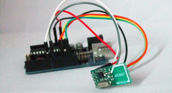
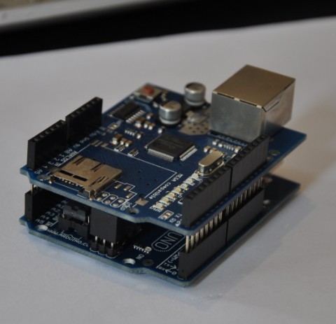
Zigbee is a good wireless solution for arduino long time, however, it is expensive. NRf24l01 only $1.5 per piece at Electrodragon, you can find it here. Not only cheap, this module is also high speed (2Mbps), Low power consumption (1uA at standby mode) and quite far communication distance (20-30 meters), you will like it! The tutorial and code is available here!
How to Say hello to another Nrf24l01?
We use library mirf which is easy for new user to start.
Step 1. you will always need to include the libary as follow
[c]
#include <SPI.h>
#include <Mirf.h>
#include <nRF24L01.h>
#include <MirfHardwareSpiDriver.h>
[/c]
Step 2. Setup up for each Nrf24l01, this is also the same for almost any Nrf24l01. The payload is just set to the maximum length 32 bytes. SPI also set up.
[c]
void setup(){
Serial.begin(9600);
Mirf.spi = &MirfHardwareSpi;
Mirf.init();
Mirf.setTADDR((byte *)"serv1"); //TADDR should change into RADDR if it is a receive
Mirf.payload = 32;
Mirf.config();
Serial.println("Beginning … "); // or "Listening …" on sever
}
[/c]
Step 3. Send Hello in bytes from transmitter to other one in every 0.5 second, this is a simple loop part in transmitter. The char “hello” is sent.
[c]
void loop(){
Mirf.send((byte *) "Hello");
delay(500);
}
[/c]
The code of the same meaning, remember array is zero indexed, so the array size should always plus one
[c]
void loop(){
char a[6] ="abced";
Mirf.send((byte *) a);
delay(500);
[/c]
And if you want send int format information, the code is
[c]
void loop(){
int a[6] = {2, 4, -8, 3, 2};
Mirf.send((byte *) a);
delay(500);
}
[/c]
Step 4. Now, let receive our data on the receiver module, simply set a byte array of 32 bytes length, when data is not sending and data is ready,
we receive it and print it in byte format.
[c]
void loop(){
byte data[32];
if(!Mirf.isSending(); Mirf.dataReady()){
Serial.println("Got packet");
Mirf.getData((byte *); data);
Serial.print(data[0], BYTE); //h
Serial.print(data[1], BYTE); //e
Serial.print(data[2], BYTE); //l
Serial.print(data[3], BYTE); //l
Serial.print(data[4], BYTE); //o
Serial.println("");
}
}
[/c]
If you send int format data, the receive code should be
[c]
void loop(){
int data[32]; // here is int format
if(!Mirf.isSending(); Mirf.dataReady()){
Serial.println("Got packet");
Mirf.getData((byte *); data);
Serial.print(data[0]); //2
Serial.print(data[1]); //4
Serial.print(data[2]); //-8
Serial.print(data[3]); //3
Serial.print(data[4]); //2
Serial.println("");
}
}
[/c]
Now you know the data is transferring between Nrf24l01 as binary, and you can make a data array to get it and print it in byte format.
This is just the most simple communication function for this module, more functions and tutorials will be available soon.

Comments (25)
can i connect this module to microcontroller serial port?
if yes, HOW?
Hello aamir,
I don’t think this module can work with MCU serial port, but it works with SPI protocol, most of MCU support it. Can you tell me what you use? then we will make relevant information for you.
if i am using Arduino Mega,
— can you advise how to connect the SPI?
— do I need to change the codes or any *.h files?
thanks
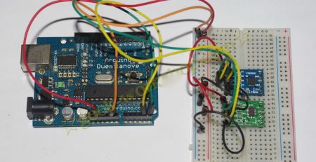
Hello Eric, the pins are:
NANO 328:
MISO -> 12
MOSI -> 11
SCK -> 13
Note that the pin numbers are not in order.
Quote
MEGA 2560:
MISO -> 50
MOSI -> 51
SCK -> 52
Note that the pin numbers are in order.
It should be nothing need to be changed in any files, only make sure the pins are correct, but I am not sure about it, I don’t use a arduino Mega, sorry, mate!
There is another blog post about some issues of Nrf24l01 with arduino MEGA or NANO, please take a look and hope it helps you.
http://www.bajdi.com/playing-with-nrf24l01-modules/
i used two Arduino Mega to test the codes of transmitter and receiver. On the receiver side, when I open the Serial Monitor, I see “Got Packet”, but there is nothing else shown. What could be the reason? Thank you very much.
Hello Eric, it’s really hard to say. I suggest you to get a arduino UNO and set it as a transmitter, let it talk with your arduino mega as a receiver, see if it works. and also do UNO as a receiver and mega as a transmitter to exclude any problems between.
does this module differ from the NRF24LP-D01? or is this a replacement?
thanx
Hi Bluebee,
It’s the same one!
My NRF24L01’s came without proper silkscreen and a two-row 8-pin header (pin 1 marked). As a result I have no idea which pins are which for SPI… Anyone have any ideas?
Hello TristanJ,
Please take a look at the pin definition on thispage: https://www.electrodragon.com/w/index.php?title=NRF24l01#Pin_Definition
I’ve fork a version of RF24 with support for both Arduino and Raspberry Pi at http://arduino-for-beginners.blogspot.com/2013/02/setup-nordic-nrf24l01-rf-modules-to.html
Links to my forked RF24 repo at summary links…
Hi guys,
I’ve used this module in several projects and it’s absolutely fantastic, I’m now looking to see if I can use it to wirelessly program the Arduino much like the “BlueSMiRF” from Sparkfun but at a fraction of the cost. I’ve been doing some research on the area but most people seem obsessed with XBee or ZigBee and ignore the little gem that is the NRF24L01+, any ideas?
As the module runs on 3.3V, does the Arduino have to be running on 3.3V too, unless you’re using a logic level converter?
Or does the module just cope with 5V inputs?
Hey Andy,
You can get the 3.3V from the arduino, nest to the 5v connection
HTH
(I forgot to tick “Notify me of follow-up comments by email”. Had to make another comment or I’d never know if there was a reply. Surely, that should be on by default?)
Useful tip, Steve, but that’s not really the issue.
Most logic chips and MCUs can only accept inputs that are less than or equal to the supply voltage (Vcc or Vdd). Some allow it to be a little bit more, but usually only something like 0.25V or 0.5V above Vcc / Vdd.
I’ve since read, somewhere, that the NRF24L01 can accept inputs from a chip that’s working off 5V (which would normally mean inputs in the region of 0V to 5V). I haven’t tried it yet though. I do have some spares, just in case it’s wrong.
Hi, please, consider correct the code. There are some tipos.
This one compiles ok
#include
#include
#include
#include
void setup(){
Serial.begin(9600);
Mirf.spi = &MirfHardwareSpi;
Mirf.init();
Mirf.setTADDR((byte *)”serv1″); //TADDR should change into RADDR if it is a receive
Mirf.payload = 32;
Mirf.config();
Serial.println(“Beginning … “); // or “Listening …” on sever
}
void loop(){
int a[6] = {2, 4, -8, 3, 2};
Mirf.send((byte *) a);
delay(500);
}
void received() {
byte data[32];
if(!Mirf.isSending() && Mirf.dataReady()){
Serial.println(“Got packet”);
Mirf.getData((byte *) data);
for(int i=0;i<sizeof(data);i++)
{ Serial.print(data[i]);}
}
}
Hi there, how to connect several NRF24l01 clients to one unique server and run a kind of client/server application?
The way you show here, I think if I send the data from one module, all the other modules will receive the same information, at the same time.
Is that correct?
Thanks for sharing your knowledge and time.
Hey ,
I think this is what you have been looking for http://maniacbug.wordpress.com/2012/03/30/rf24network/
I have to say I must send him so “Big thanks” as that seems to be a great apprach for sensor network 😀 wireless of course!
nRF24L01 rocks. I was able to have a Atmega+nRF24L01 talk to another Atmega+nRF24L01 as well as a BeagleBone Black talk to an Atmega+nRF24L01. For a $1.99 nRF24L01 is a little breakout board that can.
Hello Yogesh,
That item is a bit expensive and not very properly for making product, we will add it later, so you can take a try.
Thank you.
Hi admin
dos this chip connect identically to MCU in both side (e.g. RX & TX)? I mean nrf24l01 ports connect to same port on MCU.
They seem like they might be noisier.
Nothing against the NRF, but you cannot compare a protocol like Zigbee (or Thread or any other mesh network protocol for that matters) with just the NRF24 device. A NRF24 cannot ‘heal’ it’s lost link when a node drops out… not on itself that is. Sure, one could hack some code to do that, but then you’re back to a mesh network again 🙂
I am looking exactly for such a library that would do Thread or Zigbee or a completely different mesh network protocol (hell I dont care about names as long as it’s self healing) via NRF24 devices.