CC1101 RSSI and LQI Test
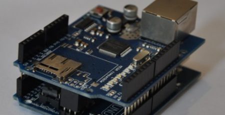
This test is based on our basic CC1101 board, it is the basic version, not the highest signal strength, nor using the on-board MCU to simply the communication to serial port. So this board works at SPI originally.
First what is LQI and RSSI, we copied an answer from this link to here briefly:
LQI (Link Quality Indicator) is a metric of the current quality of the received signal. The LQI gives an estimate of how easily a received signal can be demodulated by accumulating the magnitude of the error between ideal constellations and the received signal over the 64 symbols immediately following the sync word. LQI is best used as a relative measurement of the link quality (a low value indicates a better link than what a high value does), since the value is dependent on the modulation format.
RSSI is a signal strength indication. It does not care about the “quality” or “correctness” of the signal. LQI does not care about the actual signal strength, but the signal quality often is linked to signal strength. This is because a strong signal is likely to be less affected by noise and thus will be seen as “cleaner” or more “correct” by the receiver.
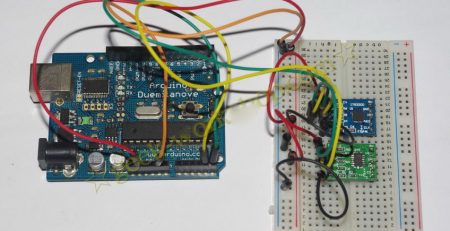
So here is the test, first setup you can find on our wiki page link here, it is in the “Arduino Library Panstamp Use Guide” section. Wiring the CC1101 module to arduino with 7 pins as below:
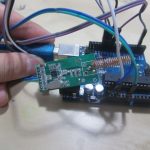
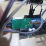
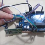
Download the library and uploaded the demo code, on the receiver end, we can check the signal strength from the serial port.

So here how we tested the signal quality, first we will put the receiver and transmisster next to each other, and then move the transmitter to next room which is about 3-4 Meters distance, then further to a more far room about 4-6 Meters, the distance is roughly said.
From the result we can see RSSI drop steadily, and LQI will start to drop when it goes to the far room.
- First they are closed and result is:
CC1101_LQI 17
packet: len 10 data: 5 0 0 1 0 5B 67 F9 24 3F .
packet received
CC1101_RSSI 114
CC1101_LQI 17
packet: len 10 data: 5 1 0 1 0 5B 67 F9 24 3F .
packet received
CC1101_RSSI 114
CC1101_LQI 18
packet: len 10 data: 5 2 0 1 0 5B 67 F9 24 3F .
- Then in the next room:
CC1101_LQI 17
packet: len 10 data: 5 0 0 1 0 5B 67 F9 24 3F .
packet received
CC1101_RSSI 91
CC1101_LQI 17
packet: len 10 data: 5 1 0 1 0 5B 67 F9 24 3F .
packet received
CC1101_RSSI 95
CC1101_LQI 19
packet: len 10 data: 5 2 0 1 0 5B 67 F9 24 3F .
packet received
CC1101_RSSI 95
CC1101_LQI 17
packet: len 10 data: 5 3 0 1 0 5B 67 F9 24 3F .
- Then finally the further room:
CC1101_LQI 0
packet: len 10 data: 5 36 0 1 0 5B 67 F9 24 3F .
packet received
CC1101_RSSI 74
CC1101_LQI 16
packet: len 10 data: 5 37 0 1 0 5B 67 F9 24 3F .
packet received
CC1101_RSSI 79
CC1101_LQI 16
packet: len 10 data: 5 38 0 1 0 5B 67 F9 24 3F .
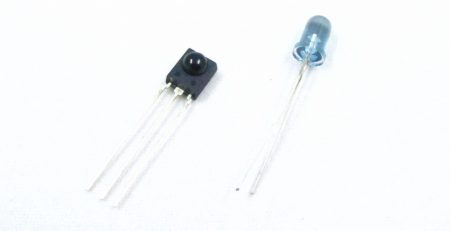
Furthermore, we also have SI4432 wireless module, CC2500, RFM22B (not yet available), etc in store can also provide RSSI function. Most these modules only need to read its register to get the RSSI value.

Comments (2)
you have mentioned about getting RSSI value using cc2500 chip.I am using an attiny85 and a cc2500 chip.At the same time im using arduino to code is it possible for you to send me some example codes that you have used in your project and that would be really grateful.
Beauty! You save lots by giving up the brand name.