Sale


![ESP LED Strip WIFI/BT Control Board [ESP-MOD] - Image 1](https://www.electrodragon.com/wp-content/uploads/2022/01/ESP32-C3-WROOM-LED-Strip-Controller-01-400x400.jpg)
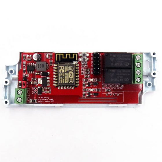
![ESP LED Strip WIFI/BT Control Board [ESP-MOD] - Image 2](https://www.electrodragon.com/wp-content/uploads/2017/06/ESP-LED-Strip-Board-01-560x560.jpg)
![ESP LED Strip WIFI/BT Control Board [ESP-MOD] - Image 3](https://www.electrodragon.com/wp-content/uploads/2017/06/ESP-LED-Strip-Board-02-400x400.jpg)
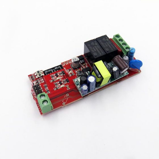
![ESP LED Strip WIFI/BT Control Board [ESP-MOD] - Image 4](https://www.electrodragon.com/wp-content/uploads/2017/06/ESP-LED-Strip-Board-03-400x400.jpg)
![ESP LED Strip WIFI/BT Control Board [ESP-MOD] - Image 6](https://www.electrodragon.com/wp-content/uploads/2022/01/ESP32-C3-WROOM-LED-Strip-Controller-02-400x400.jpg)
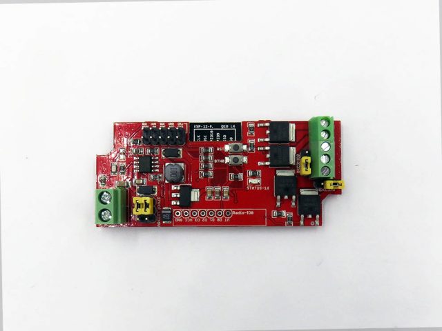
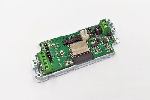
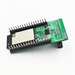
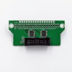
ESP LED Strip WIFI/BT Control Board [ESP-MOD]
Price range: $3.00 through $7.50
- Description
- Additional information
- Reviews (36)
- Enquiry2
Description
Available Versions:
ESP-12F
- Based on ESP8266 Wifi IC, ESP-12F module.
- Product SKU NWI1124
ESP32-C3-WROOM-2:
- Product SKU NWI1126
- Based on official ESP32-C3-WROOM
- Long life time as it is an officially module from espressif
- Which support bluetooth 5, better LED drive capablity, fater speed, and more
- Flash version 4MB
- Only slightly expensive than esp8266, you can also buy this ESP32 module from us.
- Lead out all extra pins for extra extension purpose
- ADD vertical USB port, no ganurtee it can work well, could be buggy
- Available both IO9 PROG Button and EN button
- Add ADC analog sensor port from customer god ideas
ESP32-C3-12F (lifetime over now, N/A): Product SKU NWI1125, Based on ESP32-C3-12F, Flash version 2MB
Drive Features:
- Support one channel RGB LED strips (can also be used for three channels LED strips)
- Support one extra channel white LEd strips.
- Support one channel WS2812 LED strips or ring, (select by jumper, can not work with RGB in the same time)
- On board Mosfet control is FR1205, support up to 44A/55V, for low light 5050 white led strip is about 0.4A 12V(5W), so technically support up to 100 meter per channel.
- Power Supply by DCDC MP1584:
- Input voltage 6-27V, also power LED strip
- If LED strip is 12V, input voltage should be 12V.
- For WS2812, input voltage should use 5V.
Package Inlcudes:
-
- Main control board
- Plastic case kit (smaller than ESP relay board.)
- DC5.5-2.1CM power input cable
- RGB connecting cable
- normal 5050 white LED strip (10CM width) cable.
Additional information
| Weight | N/A |
|---|---|
| ESP |


![ESP8266 SMD Breakout Board R2 [version]](https://www.electrodragon.com/wp-content/uploads/2015/06/esp-smd-adapter-board-2.1-560x560.jpg)


![[Retired]A20 Mini Dev Board, GSM GPRS WIFI Camera](https://www.electrodragon.com/wp-content/uploads/2016/12/A20-development-board-400x400.jpg)


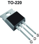
![2PCs MOSFET [IRF540N, IRF9540]](https://www.electrodragon.com/wp-content/uploads/2012/07/Mosfet-IRF-series-400x400.jpg)
![[Retired] ESP-13 ESP8266 Wifi Module](https://www.electrodragon.com/wp-content/uploads/2015/04/ESP-13-ESP8266-Wifi-Board-560x560.jpg)
Freddy –
I bought five of them. With the original software I didn’t get the Leds controlled. Not via MQTT and also not via the HTML commands.
The solution was to install EspEasy with the RGBW plugin from the Playground.
Now everything is running as expected!
For the next revision, it would be nice if the voltage input terminal are marked with Vcc and Gnd.
andreaslindegger (verified owner) –
Cool thing, but the high frequency noice could be desturbing. Can we set the switching frequency somehow? Maybe with that we could make the noice less desturbing (higher then 20kHz)
Albert (verified owner) –
These are excellent little boards. Flexible voltage regulation and very tidy enclosure – a great way to make compact and polished IoT projects with only one power supply. I’ve started using these for non-LED strip projects because they’re just so darn versatile. I’ve got a couple driving SK6812 RGBW strips with no issues.
Pre-soldered male headers and IO0 button make re-flashing easy. Screw terminals are convenient for testing but I would recommend instead soldering to the legs of the terminals, which are available on the underside of the board. It’s even not too hard to solder directly to the pads on the ESP8266 module itself.
Would love to see Vcc and Gnd marked as per a previous review – luckily this is easy to work out with some continuity testing.
Pierre (verified owner) –
I bought 5 pieces and the older version was delivered, with the buttons aligned on the esp8266, it is not working. can you help me?
Chao (store manager) –
Hi, The function of the buttons never changed, one is IO0 for programming, one is reset button. IO0 is also programmable and do nothing if not program it. Please let me know more details why it is not working. Please email to in**@***********on.com, I will also email you for details. Thank you.
Rowan Etkinson –
PWM noise is really annoying
Spectrumero –
This works perfectly with Esphome using a RGBW 12V led strip, this is the config yaml you can use:
———
esphome:
name: nameyourledstrip
platform: ESP8266
board: esp01_1m
# Enable logging
logger:
# Enable Home Assistant API
api:
ota:
password: “xxxx”
wifi:
ssid: “YourWIFISSID”
password: “Your_password”
# Enable fallback hotspot (captive portal) in case wifi connection fails
ap:
ssid: “XXX Fallback Hotspot”
password: “XXXXX”
captive_portal:
light:
– platform: rgbw
name: “Livingroom Lights”
red: redpin
green: greenpin
blue: bluepin
white: whitepin
output:
– platform: esp8266_pwm
id: redpin
pin: 15
max_power: 100%
– platform: esp8266_pwm
id: greenpin
pin: 12
max_power: 100%
– platform: esp8266_pwm
id: bluepin
pin: 13
max_power: 100%
– platform: esp8266_pwm
id: whitepin
pin: 14
max_power: 100%
kender –
Used it with addressable LEDs and WLed firmware, works great
Robert –
Whatever I do I can’t get these things into flash mode…
Denis (verified owner) –
Can be easily upgraded to Tasmota firmware:
===
Tasmota
Program Version 10.0.0(tasmota)
Build Date & Time 2021-10-19T08:23:49
Core/SDK Version 2_7_4_9/2.2.2-dev(38a443e)
Uptime 0T00:01:48
Flash write Count 32 at 0xFA000
Boot Count 9
Restart Reason Software/System restart
Friendly Name 1 Tasmota
AP1 SSId (RSSI) OpenWrt (62%, -69 dBm) 11n
Hostname tasmota-6D0E4A-3658
MAC Address 5C:CF:7F:6D:0E:4A
IP Address (wifi) 192.168.0.8
Gateway 192.168.0.1
Subnet Mask 255.255.255.0
DNS Server1 192.168.0.1
DNS Server2 0.0.0.0
HTTP API Enabled
MQTT Host mqtt.lan
MQTT Port 1883
MQTT User zigbee2mqtt
MQTT Client DVES_6D0E4A
MQTT Topic tasmota_%06X
MQTT Group Topic 1 cmnd/tasmotas/
MQTT Full Topic cmnd/tasmota_6D0E4A/
MQTT Fallback Topic cmnd/DVES_6D0E4A_fb/
MQTT No Retain Disabled
Emulation None
ESP Chip Id 7147082 (ESP8266EX)
Flash Chip Id 0x1640C8
Flash Size 4096 kB
Program Flash Size 1024 kB
Program Size 612 kB
Free Program Space 388 kB
Free Memory 27.1 kB
===
Denis (verified owner) –
Tasmota config:
“`
{“NAME”:”LEDBoard RGBW”,”GPIO”:[0,0,0,0,0,0,0,0,418,417,419,416,288,0],”FLAG”:0,”BASE”:18}
“`
Notrial –
did anyone manage to flash WLED or ESPHome on the ESP32 version?
Chao (store manager) –
Hi Notrial,
From other users feedback, WLED seems not working yet, and don’t know for Tosmota.
We didn’t try yet. We only did test with all the basic functions.
Thank you. Best regards,
Tony N (verified owner) –
I bought two and they are working fine with wled. I am disappointed that there is no level shifter / LLC for the addressable output as well as being limited to the jumper current rating (3A?) for PWM LEDs. Flashing is a bit tricky. Still have not nailed it, but I can just OTA now.
Notrial –
Hi Tony N,
So you are saying max output is 3A?
So you managed to flash WLED? Can you explain the tricky part, please?
Much appreciated!
Nefi Alfonso Segarra (verified owner) –
Good product, happy with it
Scott Hunt (verified owner) –
You can flash with an arduino Uno as interface. Rx to Rx, Tx to Tx, IO0 to ground, 3.3v or 5v to 3.3 or 5v, and ground to ground. I used tazmotizer to flash WLED, once Arduino was setup(Have to download ESP8622 board manager – and there is even a setup for electrodragon). I think I still had to click the IO0 button to start the flash enable.
Mark Jacobs (verified owner) –
The esp32 version goes into bootloop when flashed with any bin. I will have to remove the chip and replace with 8266
Chao (store manager) –
Hi Mark, we have manually flashed all the boards and tested with led strips, so it should be no problem. Please contact by email to solve any problems.
Robert –
I bought the ESP32 version from CloudFree.
The claimed 44 amps per channel is dangerously overstated. After just 10 minutes of powering about 4 amps worth of LED strips spread across 2 channels, the box got so hot that I couldn’t touch it for more than a second or so, and the power jumpers melted. I understand that this is a very cost-optimized device, but the description needs to be realistic about what it can safely support, which I would guess is in the range of 2.5 to 3 amps input power for ALL channels.
I was able to minimize the total non-MOSFET voltage drop to less than 10% of the MOSFET’s voltage drop by replacing all of the jumpers with solder bridges and adding a pair of 20ga bodge wires running the length of the board. The device has performed well since making these changes.
My boards also came without reset buttons installed, making it more difficult to flash custom firmware. This is a one-time activity, so it’s not so bad.
I would love for there to be a controller of equivalent functionality that can safely deliver 3+ amps of power per channel. Fused, no headers/jumpers carrying high current, larger terminal blocks, thicker copper on the PCB, and mounting holes. Even at 4x the price of this controller, it would be worth every penny.
Mike Toggweiler (verified owner) –
ESP32 version successfully flushed following those instructions as the flash image size is only 2MB:
https://community.home-assistant.io/t/esp32-c3-boot-loop-2mb-flash/466311/3
However was not yet able to determine PIN out layout for ESP32 version. Any suggestion?
Mike Toggweiler (verified owner) –
Found the answer myself: https://albert.nz/esp32-led-strip
Chao (store manager) –
Thanks for the review. We are selling 4MB version now at the same price. And we will improve the power delivery capability as you suggested in the future. Thank you!
William Weilep (verified owner) –
Ordered the esp32-c3-12frisv-4m 4M version and received the 2M version instead, no OTA capability as a result. Seems they mixed up supply.
[email protected] (verified owner) –
I was able to flash WLED using the new USB port and the INSTALL WLED web site. Seemed to work and it said flashing complete. WLED got an IP address and I was able to talk to it with a web browser. The problem is, I have no output on the screw terminals.
I have an oscilloscope and I can see the chips output data on the IO2 pin but not on the data output screw terminals.
I have the output jumpers set to ws2812 and GROUND. Pins 3, 4, and 5 are supposed to be GRD, Data, and 5 Volts but pin 3 has 5 volts pin 4 has nothing and pin 5 has 5 volts.
Both input options are set to 5 volts.
I have spent a lot of time trying to get this unit to work since i am impressed with the packaging and versatility, but so far i have no output on the screw terminals. Anybody have any idea what i might be doing wrong.
I have purchased another unit to try but it is not here yet.
Doug
Chao (store manager) –
Hi Doug, It is our mistake, the wiring diagram is not clear enough, please take a look at here: https://w2.electrodragon.com/Board/NWI/NWI1126-DAT/NWI1126-DAT.md
The pin 3/4/5 definitions should be DAT-GND-5V, not GND-dat-5V. Thank you!
Adam Hussey –
Figured out WLED on the ESP32-C3 finally. The first hurdle to climb was actually getting the WLED firmware installed. For whatever reason the only thing that worked was the web flasher on my 2nd PC. First one didn’t work, no idea why. I flashed with a usb-ttl using 5v.
All of the data documents were pretty confusing and I had a hell of a time interpreting them. My LED set is a WS2811 and it took me too long to realize that this follows the same rules as the WS2812 documentation with regards to setting the jumper pins. Then I wired everything up as the documentation says for the WS2812, which were V+,V-, and data to the bottom 3 terminals. Then still had no luck, I know for a fact that it was wired correctly and I confirmed with my multimeter – so the issue had to be with which data pin was mapped. Everywhere in the documentation it mentions “IO2” is the GPIO, except for a small line on the NWI 1125 data sheet that literally says
“IO02 = IO10 = WS2812”. Ok,,, so lets try GPIO 10 and see if it miraculously starts working, and by golly it did. We’re in business!
P.S. I ordered this module from CloudFree.IO – check them out if you haven’t heard of em!
Nikola Schmidt (verified owner) –
Anyone with yaml configuration for ESP32-CR-WROOM ?
Nikola Schmidt (verified owner) –
The correct PIN configuration and yaml code for ESPHOME for ESP32-C3-WROOM is as follows:
output:
– platform: ledc
id: red_channel
pin: GPIO7
– platform: ledc
id: green_channel
pin: GPIO6
– platform: ledc
id: blue_channel
pin: GPIO5
light:
– platform: rgb
name: “LED Strip”
red: red_channel
green: green_channel
blue: blue_channel
Andreas (verified owner) –
Hello, just received my Esp32 wroom version. Works fine until now with esphome.
Is there a possibility to use the spare io for a i2c interface? I tried io2 and io3 but then it does not start anymore.
Still a great product! Thank you!
chao –
Hello Andreas, I just made a demo video, you can find it here:
https://youtube.com/shorts/UG-1v1mZk8A?si=PcT6opcI4V1srDCq
Demo code please find
https://github.com/Edragon/Arduino-ESP32/tree/master/Sketchbook/interface/interface-IIC-scan
and
https://github.com/Edragon/Arduino-ESP32/tree/master/Sketchbook/interactive/OLED/SSD1306SimpleDemo
IO 2 and 3 works OK, maybe also can use 2 + 8 because these two both have pull-up.
We have network problem so far to diagnose using epshome, so only arduino demo here.
best regards,
Marcel (verified owner) –
received my Esp32 C3 wroom version. Works fine with Wled ,and figured out that thegpio 9 is the pin that works fine. both jumpers on 5volts and jp8 and jp9 both on top
Gordon (verified owner) –
Works OK, I am using with 5050 rgb leds with 4 wires, the problem I am having is the LEDs will not turn off. Using either esphome or WLED even when leds’s are off there is still a small amount of light being emitted by the LEDs. Anyone know how I can fix this?
Steve (verified owner) –
I have exactly the same issue as Gordon above. Blue LED just stays on a small amount when the light is off in ESPhome. Not a huge issue (other than the presumable wear on the LED strips) as barely noticeable but would like it if this could be resolved. I have 10mm BTF-FCOB RGB’s at 24V plugged into the board.
So far, I’ve installed onto three boards and have the same issue with each. Have attempted GPIO4(g), GPIO5(r) and GPIO6(b). Have also varied with GPIO5(b), GPIO6(g) and GPIO07(r) and the issue persists seemingly no matter the order.
The service from electro dragon has been fantastic and the boards are of really solid quality. Not much choice if you are looking for a non-DIY ESP32 based board. Just wish this LED off issue could be resolved.
lukix (verified owner) –
I have ordered 10pcs of this fantastic controller. Using Tasmota FW in it, with combination of HomeAssistant. Working absolutely fantastic and reliable.
I have noticed 2 issues:
– one is the same as Gordon and Steve have. Basicaly 1st PWM channel is not turned off completly. If you connect LED strip (24V) on it, you will notice it is ON. CAn not be turned off. Probably there is very low current, because LED strips shines very dimm, but if is dark, you notice it.
– second issue is, that when the controller is turned off, and you turn it on it wil very shortly flash – than turn off, and thatn turn on again.
Fantastic product, but would be nice if is little tuned to be 100% working as you expect.
Chao (store manager) –
Sorry for the problems. The circuits probably need better fine tune.
I added a few analaysis for these issues here in section “circuit guides”: https://w2.electrodragon.com/gollum/search?q=mosfet-dat.md
We will try to represent the issues here and see if we can further improve it.
Thank you very much!