


![RGB Matrix Panel Drive Interface Board for ESP32 DMA [VER] - Image 1](https://www.electrodragon.com/wp-content/uploads/2020/12/ESP32-I2S-DMA-Matrix-LED-Drive-04-400x400.jpg)
![RGB Matrix Panel Drive Interface Board for ESP32 DMA [VER] - Image 2](https://www.electrodragon.com/wp-content/uploads/2020/12/RGB-Matrix-Panel-Drive-Interface-Board-for-ESP32-DMA-01-400x400.jpg)
![RGB Matrix Panel Drive Interface Board for ESP32 DMA [VER] - Image 3](https://www.electrodragon.com/wp-content/uploads/2020/12/ESP32-I2S-DMA-Matrix-LED-Drive-01-400x400.jpg)
![RGB Matrix Panel Drive Interface Board for ESP32 DMA [VER] - Image 4](https://www.electrodragon.com/wp-content/uploads/2020/12/ESP32-I2S-DMA-Matrix-LED-Drive-02-400x400.jpg)
![RGB Matrix Panel Drive Interface Board for ESP32 DMA [VER] - Image 5](https://www.electrodragon.com/wp-content/uploads/2020/12/ESP32-I2S-DMA-Matrix-LED-Drive-03-400x400.jpg)
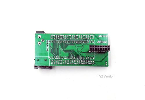
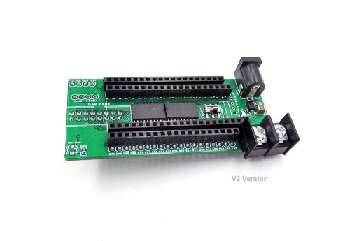
RGB Matrix Panel Drive Interface Board for ESP32 DMA [VER]
Price range: $3.80 through $4.00
- Description
- Additional information
- Reviews (20)
- Enquiry2
Description
Please note only certains panel with tested panel chips work with this board and code method, refer to the wiki page note. Other not-working panels should use this by ESP32
Board 2 Version 2 IDD1027:
- Based on our NWI1244 ESP32-S3 development board, or similar waveshare board
- No more on-board switch for board selection.
- 8.5mm power cable terminal and DC barrel connector all plug in from the right side now.
- All the rest features remain all the same.
- New pin definitions please refer to the wiki page.
Board 1 Version 1 IDD1013 Features:
- Use longer pin header for plug-in input pins.
- Support ESP32-DEVKITC or ESP32-PICO board, you can also find them in our store.
- Lead out HUB75 pin4:E and pin8:E pins
- Pin8:E can be selected by jumper for both boards.
- Further lead all pins for ESP32-DEVKITC
- Power supply via DC5.5-2.1 jack header or 8.5mm screw connector.
- Current selling version is V2, check wiki page below for details
- Documentation please see on this page.
Matrix drive board series: by ESP8266, by Arduino, by raspberry pi, by raspberry pi V2, by ESP32, by ESP32 DMA
Additional information
| Weight | N/A |
|---|---|
| Versions | Board-1, Board-2 |


![USB Wifi Wireless Wlan Adapter Module RTL8188 [Mode]](https://www.electrodragon.com/wp-content/uploads/2014/01/rtl8188eu-wireless-card-560x560.jpg)


Charly86 (verified owner) –
I’m fan over years of electrodragon’s products but this one I don’t have words to describe this crappy one, .
– First, lot of hand soldering connector and they should have been made by a rookie, not nice, even not sure they will do the job (if I get this to work)
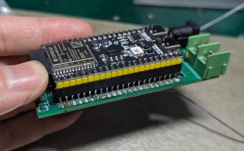
– We don’t know which side to plug ESP32, should have been complicated to put a picture with the device plugged in so we can know how to plug?
– So trying to match with silkscreen pin name to plug ESP Pico Dev kit? no way, no silk on PCB, don’t try also to read 5V or GND on big connector there is no silk either
– So my guess, check the powering and placing on documentation? no way either, no documentation except for software configuration.
Going immediately to case “things to get out one day when it will have basic documentation”
Chao (store manager) –
Hello!
Sorry for the bad documentation ! We are indeed not doing well no this.
Please take a look on this video, https://youtu.be/sVVVZQoz2u4
For PICO pin descprition please only change CLK to 21, and pin D to IO22, if you don’t use E-line, that is all, no need any extra soldering works. You can upload the code, run and get the same result.
The USB port should on the same side of the DC power port.
I am not sure anything else if still not clear, if so please just let me know. The PCB silk print is indeed crap, we have to fix on the next version.
Thanks for the feedback!
Charly86 (verified owner) –
Dear Chao,
Thanks, it’s so much better with a video :-).
May I suggest adding I2C “classic” pinout (VCC/GND/SDL/SDA) to be able to plug something like that
https://www.electrodragon.com/product/ambient-light-intensity-sensor-tsl2561-breakout/
to control luminosity, would be awesome
Thanks
Charly86 (verified owner) –
Chao,
Would you mind post the schematics somewhere, I just spend some time to get some other GPIO of the Pico D4 (to add sensor) wired but looks like they are not wired on external header, only the one for DevKitC correct?
thanks
Chao (store manager) –
Hi, thanks for the suggestions!
Will add the I2C port, also it is necessary to add logic shifter for logic level. This will be done as the final verison.
Schematic added to here: https://www.electrodragon.com/w/ESP32_DMA_RMP
We usually don’t know what documents is needed or what information is missing, if you need please just drop message or email. Thank you again!
Charly86 (verified owner) –
Chao,
Many thanks, that is was I was suspecting, GPIO34 (and others) of the Pico are not routed anywhere (I mean the external header GPIO34 is connected to DevKitC GPIO34 and NOT also on Pico GPIO34. Good to know
Awesome for level shifter nice idea. If you need beta testers, I’m in.
By the way connector to plug to Matrix is not really robust (and too high) may be something like that will be better.
https://www.aliexpress.com/item/32948722278.html
From my point of view, It would be better to have option to buy with this connector not soldered, because lot of time one of these works perfectly
https://www.aliexpress.com/item/32656684183.html
Chao (store manager) –
Hi Charly86, Yes, thank you for the feedback again. This board is built quick and we did only focus on the devkitc, if you use a devkitc you can use all the expand pins. We will fix this for PICO pins, also for the connectors. But the short connectors won’t work, it has interferences with the RGB panel, you never know if the connection is good enough or not. Thank you again. Once new board is ready I will arrange to send you free samples.
Charly86 (verified owner) –
Chao
Many thanks,
Just take a look on this, I created this shield some time ago https://github.com/hallard/WeMos-Matrix-Shield
Could be interesting to have footprint for the LDR going to analog pin, you just need to add one 10K resistor between analog input and ground and then put LDR between analog pin and 3.3V. Cheap solution to control matrix brightness from ambiant light. I’ve done this on you board I received and it works fine, I’ll post a picture later and a sample code to main repo.
ErikW. (verified owner) –
The Matrix Drive does, what it is supposed to do but..
I wasn‘t able to get a I2C port work simultaneously with the Matrix.
Since my only gole with the Drive was to display CO2, temperature and humidity, I don‘t know what to do with this Matrix Drive.
I will write a new review, if I find a solution for this/
Chao (store manager) –
Hi ErikW, The board lead out all pins for devkitc, but not for PICO
If you have problem to use the other pins, please use esp32 devkitc, or please wait for our next version. Sorry this is not clear in the product description. If you need please contact us by email for free new version.
Bogd (verified owner) –
Having a taller matrix connector is really a blessing for those who (like me) have a matrix with a plastic frame that prevents a “normal” connector from being used. It would be nice to also have the option of connecting the driver board to the matrix via a ribbon cable.
One small problem, though: the header pins used for the ESP32 board connection are… strange. They are shorter than normal 2.54mm headers (“normal” for me meaning something like this: https://www.aliexpress.com/item/1005001418544370.html ), and they grip the pins VERY tightly – making connection and disconnection a pain.
[email protected] (verified owner) –
It’s very easy to use ESP32-HUB75-MatrixPanel-I2S-DMA library on p4 64×32 panel, but not for p10 32×16. The example P6_32x16_1_4_ScanPanel.ino cannot work. There are some other libraries like SmartMatrix, but no one can get the panel work. Do you have any suggestion that can drive panel p10 32×16?
Chao (store manager) –
Hi, 1. not sure if all kinds or sizes panel can work, we only tried a few, but during our tests, some panels can not display indeed. 2. The hardware from smartmatrix is completely different with our this board, so it should work, we may make a new board to support smartmatrix library later. Best regards,
Vini –
Hi people,
Did someone made this module work with P2.0 128×64 1/32?
Using the DMA library and connecting the cables manually to the display I can draw all pixels.
But, while using the module I have 2 black lines, the PIN_E pin is connected to IO18 (and soldered).
My pins configuration, using DEVKITC (switch is also set to devkitc):
#define R1 25
#define G1 26
#define BL1 27
#define R2 14
#define G2 12
#define BL2 13
#define CH_A 23
#define CH_B 19
#define CH_C 5
#define CH_D 17
#define CH_E 18 // assign to any available pin if using panels with 1/32 scan
#define CLK 16
#define LAT 4 //The strobe signals is sometimes also called latch
#define OE 15
Am I missing something?
Vini –
its now working with P2.0 128×64 1/32.
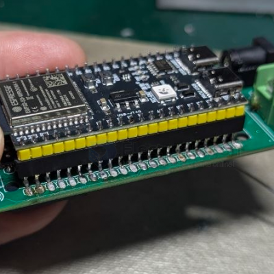
Just soldered the jumper like the picture attached.
Wiki is definitely missing some information, but it works as intended.
John (verified owner) –
I thought I ordered the original version, but received “Version 2” of this product. I can’t any of my panels to display anything with this version. I’ve tried updating the Android libraries, per electrodragon’s recomendation, no dice. All my applications run fine on the original versions of this product as well as on all my panels. Very disappointed. ESP32 Devkit C being used and yes, the selector switch is set to Devkit.
Chao (store manager) –
Hello John, We just tested today of the V2 version, it is working. Please see the demo video here: https://twitter.com/electro_phoenix/status/1635248053392375808
Please double check everything with our wiki page, it should be some tiny mistake.
John (verified owner) –
I just checked the remainder of the batch of 10 I purchased and found that 6 of them actually did work. I didn’t change anything softwarewise because it was already working on Version 1. I just plugged the ESP32 into each of the 10 as-is. My first review was a 1-star because the first three I happened to check did not work, so I assumed they were all faulty. I stand corrected, but still only have 6 working. Thanks
Destrosvet (verified owner) –
Hi,
I am still struggle with P2.0 128×64 1/32? Could you someone provide working solution or sketch? @Vini refer to some jumper but I cannot find any jumper on photo. So I am bit lost.
Thank you
[email protected] (verified owner) –
@Destrosvet in this picture you can see the jumper