


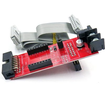
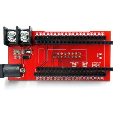
RGB LED Matrix Panel Drive Board For Raspberry Pi
$3.50
- Description
- Additional information
- Reviews (48)
- Enquiry2
Description
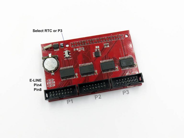
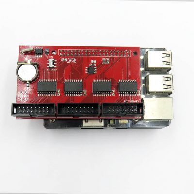
Based on the active adapter board of hzeller RPI matrix git project, full compatible and extra functions added.
- Support up to three port output to drive, P0, P1 and P2 (HUB75).
- Support Raspberry Pi 2 and 3, most pins used for matrix driving. (RPI4 need change firmware, please see comments)
- Support E-line select pins.
- On board four logic buffer chips 74HCT245
Extra Function:
- Extra on board RTC DS1307 via IIC interface, can not be used on same time with P3 port, select by switch.
- Extra on board EEPROM, on alternative IIC 25 and 26 pins I2C0 interface. Size 256KB ~512KB, a 16bytes EEPROM can work well as confirmed with users.
- Extra 5V, GND, 3V3 pin header on left top corner, you can give external power supply to RPI logic power.
Support and Shipment:
- Only can provide technical support for our type of panels, you can find matrix panel here.
- Somes types of panel drive ICN2153 2053 2038 may need rewrite driver code.
- Package does NOT include the CR1220 battery, which is not allow due to airplane security reason.
Documentation, demos, more silimilar products please see on this page.
Additional information
| Weight | 0.03 kg |
|---|


![USB Wifi Wireless Wlan Adapter Module RTL8188 [Mode]](https://www.electrodragon.com/wp-content/uploads/2014/01/rtl8188eu-wireless-card-560x560.jpg)


![RGB Matrix Panel Drive Interface Board for ESP32 DMA [VER]](https://www.electrodragon.com/wp-content/uploads/2020/12/ESP32-I2S-DMA-Matrix-LED-Drive-04-400x400.jpg)
![Raspberry Pi LCD Display w/touch [Size]](https://www.electrodragon.com/wp-content/uploads/2015/07/Raspberry-Pi-5-LCD-Display-wtouch-13-560x560.jpg)


davemaster (verified owner) –
It worked with some flickering; I’ll test with another power supply at the first attempt with a Raspberry Pi 4 2GB.
Chao (store manager) –
Hi, please double check the power supply, you need a lab power at least 3-4A. We never have this problem before, not yet sure what or where is wrong. If problem still not solve please email us in**@***********on.com.
Here is another post to use RPI4, RPI4 should be no problem: https://iot-for-maker.blogspot.com/2020/02/led-5-raspberry-pi-4-dietpi-buster.html
Chao (store manager) –
Dear customer, RPI4 default system image have flickering issue. Please try to change to DietPi Buster, and please refer to the setup on the attached post link Thanks.
nonsens (verified owner) –
Please tell me, does this board support working with P10 LED panels?
feiticeir0 (verified owner) –
Perfect board. Had it for a while now and It can drive 6 64×64 LED panels with absolutely no problem.
Recommended !
anywaytc (verified owner) –
Excellent board. There isn’t any problem to drive two 128*64 RGB LED Panels.
Ger (verified owner) –
Hello, my name is Ger from Holland and have an question.
Is it possible to connect an P5 32×64 rgb matrix to the RGB LED Matrix Panel Drive Board voor Raspberry Pi.
Thanks for an answer.
Ger
Chao (store manager) –
Yes, any size of the panel should work, p2~p10, within 64×64 matrix, but every panel has its own specification of scans, you can just try different setup in code software to find correct settings. Best regards!
Brady @ OlympianLED.com (verified owner) –
Just ordered them for testing. Will they work with Raspberry Pi Zero W?
Axel Zöllich (verified owner) –
First of all: the board’s working as driver board as expected.
But:
Six ordered board: one of them with break of switch knob (there seems to be some kind of rough handling, as the plastic bags are perforated at switch positions), two of them with 180° rotated switches, one with twisted cristal and there is solder splattered on the bottom side.
There’s not a 256k eeprom mounted (as HAT eeprom) but this is a 24C02 type what makes it 256 byte. Not usable as HAT eeprom!
The RTC is a really nice add on and works well.
toibs (verified owner) –
Great piece of kit! Simple but very effective. Have ordered over 70 of these now, and only had issues with one switch falling apart. Used on P2.5 and P5 Panels… will try on P10’s as well soon!! 🙂
Matthew (verified owner) –
Cheap and Fast but no luck. Been trying for a few weeks but can not get any panel to fully work. I have rows missing and have tried different pis and suggestions under the GitHub project.
Mine are green not red and seem to have a different chipset.
They did arrive fast though.
https://rpi-rgb-led-matrix.discourse.group/t/missing-rows-and-not-centered/410
Chao (store manager) –
Hello Matthew, Please refer to here for help: https://www.electrodragon.com/w/RPI_RMP_Guide#32×16
It is a common problem and could be solved. If you need further help please email us.
Best regards,
Angel Martínez –
Matthew
The problem is on the board. See channel D. It’s grounded. I have seen this problem on my boards. Cut the track and solder a wire between pin 12 on panel 0 to pin 12 on panel 1.
Chao (store manager) –
Hello Angel and Matthew, Yes indeed there is a problem
The line D (pin12 ) is failed and grounded by a design mistake, please cut the line as in the attached image, if you need a replacement please contact us by email in**@***********on.com.
The problem only ocur on a few sizes of the boards, probably only large size, so we failed to test this out.
Very sorry for this problem, we are about to fix all this problem for stocks right now. Thank you !!
ignacio gatica –
Mine doesnt work well it show a black bar in the middle of the image demo
ignacio gatica –
i realized i have the same problem as angel martinez
Ricebelly –
@chao,
please will you give more details how to fix this issue?
Any detailed pictures to show exactly where to cut the track(s) and where the pins needs a soldered wire etc.
Thanks in advance.
Chao (store manager) –
Hi, please see the fix of this problem here: https://www.electrodragon.com/w/MPC1073_Error
If you can not fix it manually, please email us in**@***********on.com for a new replacement instead.
Sorry for this problem again.
Ricebelly –
@chao,
from diagram: https://www.electrodragon.com/w/File:MPC1073-error-3.png
… you wired Panel 0 (pin 12) to Panel 1 (pin 10) and cut trace.
But on diagram: https://www.electrodragon.com/w/File:MPC1073-error-4.png
…. you wired Panel 0 (pin 12) to Panel 1 (pin 12) and cut trace near Panel 0.
Is it Panel 1 (pin 10 or pin 12)?
Do you have other pictures on the DIY wire fix version?
I tried wiring Panel 0 (pin12) to Panel 1 (pin 10 and then pin12)… but didn’t fix issue.
Ricebelly –
I finally have the board fixed.
This is what I did:
P0 (pin 12) to P1 (pin12) and cut trace in these two areas.
(see image)
Ricebelly –
attached image.
David Naranjo Lapuente (verified owner) –
I have bought these matrix RGB panels many times and they have always worked well, but these last ones do not work for me, the image is cut in the middle, with the four that have arrived, I need an urgent solution please, for my order #60486
Niek (verified owner) –
The bonnet works, but I am getting the same problem with two black rows. I have the fixed version, as it was sent to me, with the bypass wire. Does anyone know how to fix this?
Mickael –
Any fixes since these 2 last comments ? or is the product still defective with a black row on the screen ?
Ait –
Please tell me the exact sequence to support multiple P5 LED panels and RPi 4.
Hardware:
* Drive board: https://www.electrodragon.com/product/rgb-matrix-panel-drive-board-raspberry-pi/
* LED panel: CHIPONE ICN2153 (2727), 64×32, 1/8 scan, P5
* RPi 4/Zero 2 W
Stephan –
I ordered 2 and have tried both the fix documented by Chao and by Ricebelly – but without success. I continue to have a black strip right through the middle of the display – same as documented above.
Based on the last two reviews, this board still seems broken. Is there some fix not listed above that actually works ?
Chao (store manager) –
Hi, We tested the latest board with all the panels we can find in the market, about 8 kinds, it is no problems anymore. You can also find the latest demo image in our wiki page.
Please read the wiki page guide carefully to do troubleshooting, here https://w.electrodragon.com/w/RPI_RMP_Guide
If you still can not fix it please email.
RPI –
I have bought these matrix RGB panels many times and they have always worked well, but these last ones do not work for me, the RTC do not work with several new boards, always starts at 01.00.00.
Older boards work perfect.
Chao (store manager) –
the RTC chip DS1307 is no supply now, either too expensive or not able to be obtained. We are using HT1307A instead for now, but don’t know when could be back. This HT1307A should be full compatible as declared by the chip manufacturer, you can find the datasheet here: https://datasheet.lcsc.com/lcsc/2106071134_HTCSEMI-HT1307ARZ_C2834446.pdf
[email protected] (verified owner) –
Hello,
I already sent you a message on 03/21/2022 to ask you for an exchange because I cannot repair them.
Here is the message I sent you
“I have a problem with the “RGB LED Matrix Panel Drive Board For Raspberry Pi” that I ordered from you, none of the 4 work, I saw on different forums that there was a modification to be made but you know it’s already done, but it doesn’t work, do you have a solution?
here are the references of my order #60403.”
Thank you very much in advance 😉
Lassauce Jeremie (verified owner) –
Bonjour comment piloter les panel 64*64 merci
Lassauce Jeremie (verified owner) –
Bonjiur how to drive panel 64/64 thank you
Chao (store manager) –
Dear Lassauce, please see here: https://w.electrodragon.com/w/RPI_RMP_Guide#P3/P4_64x64_(tested)
Generally just setup the E-line, should work. We tested and have demo video on telegram, facebook, twitter.
Best regards,
Lassauce (verified owner) –
Bonjour combien de p3 64×64 peut m’être par sortie merci
Tracy (verified owner) –
Mine worked perfectly….thx
Daniel DeBusschere (verified owner) –
I’ve had a lot of success with using this with Raspberry Pi 3 and Zero W which is why it’s rated 4 stars. I would have rated 5 stars but I can’t get a Pi4 to work. I’m not sure if the problem is with this board or with the Pi/OS combo or both…
The product page says “(RPI4 need change firmware, please see comments)”. However I can’t find the firmware, details about this, or the related comments.
Nuncio Bitis (verified owner) –
This was delivered yesterday, and within 15 minutes I had it working with 2 64×32 panels to make a 64×64.
Works perfectly.
Now I just need to learn what kind of battery to use for the RTC.
Michael (verified owner) –
Hi, does this work with the falcon pi player?
Cory –
Does what it says. great price. It’s a little large and can interfere with fan operation. Your milage may vary.
I used it on a PI5 with this library: https://github.com/bitslip6/rpi-gpu-hub75-matrix, and was able to get 9600Hz operation for 64×64 panels.
There is no issue with this hardware and any PI model, only your software and OS configuration. 5 stars.
Roy McGreevy –
I am succesfully using your RGB LED Matrix Panel Drive Board HAT to drive 2 modules, from my Pi Zero 2W
It is working great, and the 3rd connector is not being used.
I also want to add your I2C to GPIO IO Expander Breaktout Board CH423 as I need 4 more GPIO pins from the Pi.
Can I, or how do I connect the expander Board to the HAT or the Pi Zero?
Or can I use the spare HAT connector to add 4 GPIO pins
Thanks.
Chao (store manager) –
Hi Roy,
1. Enable the I2C, please see here: https://w2.electrodragon.com/gollum/search?q=I2C-dat.md
2. Try the python demo code here: https://w2.electrodragon.com/gollum/search?q=CH423-dat.md
Thank you!
Bertolt Meyer (verified owner) –
Bought two recently together with their P4 64×64 matrices. I got them to work on a Pi4B with the hzeller library, BUT: For driving 64×64 matrices, this boards/shield requires soldering: You need to connect P4 to GND and P8 zu #E. Either solder two small wires or jumpers like I did (see pictures: before/after). This would be easier if the board already came with jumpers in the right place.
I found the tip here: https://w2.electrodragon.com/Board-dat/MPC/MPC1073-DAT/MPC1073-test-log-dat/MPC1073-test-log-dat.md#more-demos
However, contrary to what it says there, –led-multiplexing=0 (instead of 1) did the trick so this demo worked after soldering: sudo examples-api-use/demo –led-rows=64 –led-cols=64 –led-multiplexing=0
However, I get quite a bit of ghosting/artefacts when displaying small images and animations on a chain of just 2 64×64 matrices, even after tweaking with things like –led-pwm-lsb-nanoseconds 50 and –led-limit-refresh=240. Thus, driving two 64×64 matrices already seems to be the limit of what the hzeller library and a Pi4B can do, because of the many address lines that 64 x 64 matrices have.
P. J. Dissanayake –
Can I control a single colour p10 module?
Jonas –
hey i bought the matrix v2-2 and try to use it with a p3 64×64 led matrix. I got the same lines like in this comment section but i have the newer board. I tested a few tips from this comment page but not the cuts on the circuit board.
What can I do?
Chao (store manager) –
Hello Jonas, it is not the same board, the error board is MPC1119 in this link: https://www.electrodragon.com/product/rgb-matrix-panel-drive-board-for-raspberry-pi-v2/
but not problem, I have found your order and will arrange to send you new replacement board by today. and email you the tracking info to your email address later. Sorry for the problems! Thank you.
Phoebe –
I switched from my adafruit bonnet to this board hoping the support for parallel chains would improve performance of my 64×64 LED matrices, but this board seems to have issues displaying an image properly. There’s a double vision thing going on. The website won’t attach my image. Not sure if I received a defective board.
Chao (store manager) –
problem sovled by email:
in your case, you may need to setup the E-sel line for the chaining, Please take a look at here: https://w2.electrodragon.com/Board-dat/MPC/MPC1073-DAT/MPC1073-multiplexing-dat/MPC1073-multiplexing-dat.md