




- Description
- Additional information
- Reviews (94)
- Enquiry2
Description
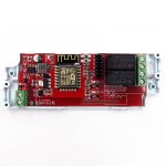
The purpose of this design is for learning how to play with the hardware and software of a IOT project, it is based on price competitive wifi module ESP8266.
Hardware Features:
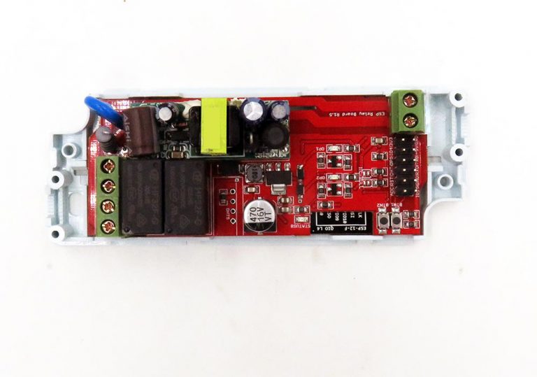
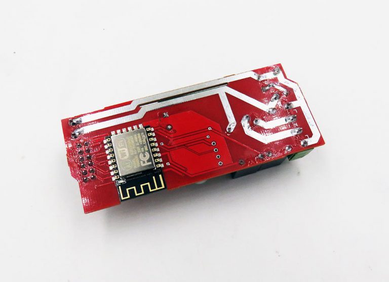
- Based on ESP-12F ESP8266 Wifi Module
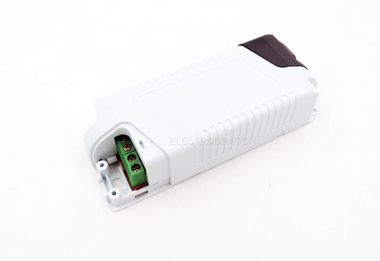
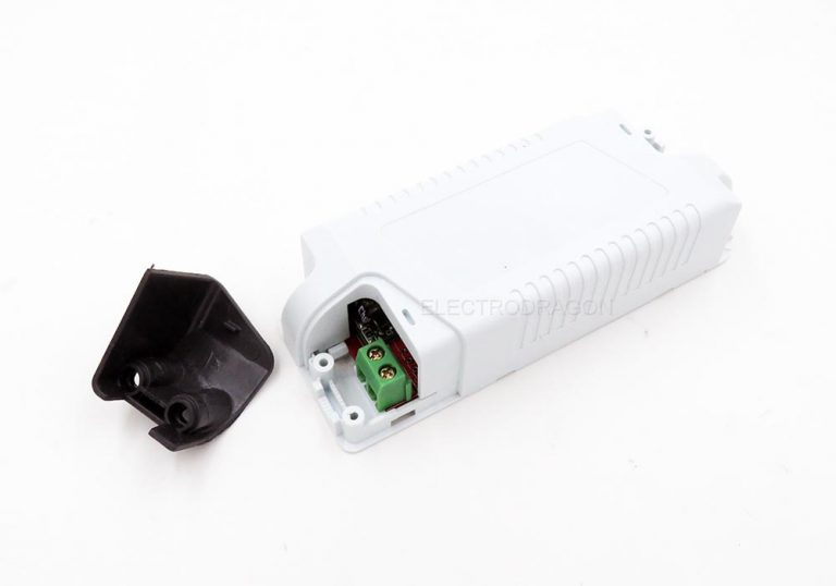
- Case general dimension is 111*42 mm.
- Two Lead out buttons BTN1 and BTN2
- One status LED, indicating connecting status in demo code
- A few lead out pins, from top (left) to bottom (right):
- Resevered design for temperature sensor DHT22
- Screw terminal which are easy for wiring output.
ACDC Power Supply Features:
- High quality ACDC power modules EDP01
- Input volatge 85 – 265VAC, 0.8A 5V DC output
Relay And Control Features:
- This relay board use one AC input, and supports two relay AC output.
- Please note the output AC power comes/connected from/with input AC power. Relay only play as on/off switch for AC power. Will be danergerous to use in any other cases.
- Relay Specification HF32F-G-5-HS
- Common – open,
- 10A
- 250VAC or 30VDC
- Two relay indication LEDs
Package include:
- Main Board and lastic enclosure
- Not including screws for sample orders only 1pcs, but included for more than 1pcs. Please prepare M2*8 or M2.2*6, etc crews by yourself.
Additional information
| Weight | 0.07 kg |
|---|---|
| ESP |
![Energy Meter HLW8032 Breakout Board V3 [VER]](https://www.electrodragon.com/wp-content/uploads/2020/12/Energy-Meter-HLW8032-Breakout-Board-basic-version-02-400x400.jpg)


![[Retired]A20 Mini Dev Board, GSM GPRS WIFI Camera](https://www.electrodragon.com/wp-content/uploads/2016/12/A20-development-board-400x400.jpg)
![Power Supplier for High Power LED [Power]](https://www.electrodragon.com/wp-content/uploads/2012/05/Power-Supplier-for-High-Power-LED-2-400x400.jpg)






![ESP8266 SMD Breakout Board R2 [version]](https://www.electrodragon.com/wp-content/uploads/2015/06/esp-smd-adapter-board-2.1-560x560.jpg)


donercagdas (verified owner) –
1 of 5 replaced v2 items was not able to flash firmware. Also button 1 is not binded to reset, instead binded to on board led. Plastic cover is not well fit.
Despite these problems, a good DIY item. I wish future replacements would cover issues.
Chao (store manager) –
Hi, Please try to press the button a little bit hard, it is too small to for pressing, but should be tested can work. Thanks.
Klaus (verified owner) –
youston i have a problem
I have 2 connected LED headlights.
both are to relay that glow pig launcher.
both are from relays,
the headlights shine faintly.
This can be seen only at night!
Why?
I have no passage measured at the relay.
Klaus (verified owner) –
fuck google tranlator 🙂
both relais are on, the headlights are shining
both relais are of , the headlight ar not completly off .
In the night you can see a litlle shining , mA of current to the Lights , i think
why ?
klaus (verified owner) –
mhh , i did not completly understand , i changed the Power in, L and N, and now is good
klaus (verified owner) –
i understand now, the power convertermodule 220v/5v has a leakage and this current goes to the headlights even when the relay is off !?
Chao (store manager) –
Hi, Which headlights do you mean? I will write you email about this issue. It maybe a code problem, the pin is not complete pull to ground to set it off, should be not a problem.
Klaus (verified owner) –
hello
sorry for my late answere.
i connect the module to the power with wall plug .
then i can not say what is L or N
Then the lights (connected on relays), are glimms .
i change the wall plug and the led is completly off, thats good.
I MUST CONNECTED the MODULE staticly!
The code is ok .
I can delete the firmware , it is the same result.
[email protected] (verified owner) –
Interesting product, we have 3 and are working with them. Please provide the R1.1 schematic on the product wiki page
Jacques (verified owner) –
This board is nice, but I cannot put 5 stars as there are several problems. I put here 3 stars and will
wait for some answers to increase the rate.
– It is very difficult to find the proper documentation for flashing the ESP8266 (I want to flash with arduino IDE).
– The RST pin of the ESP8266 is not connected. So to flash, you have to touch directly the pin of the ESP8266.
– The pull down resistors of GPIO4 and 5 are 1k, which seems to be too low to properly use them.
Up to now, I could not use them. I will try to remove the resistors.
The buttons are quite useless. A reset button would be much more useful.
Jacques (verified owner) –
There is an inversion of GPIO4 and GPIO5 in the names of the header on the schematic and board for version 1.5 of the board.
Chao (store manager) –
1. Flash arduino IDE is the same like flashing normal firmware, when arduino IDE finish compling, hold BTN2 button and board will enter into flash mode for flashing. 2. don’t have RST button indeed. 3. running a small update on this. 4. Reversed GPIO4 and 5 is a early bug of nodemcu, we just keep it ..
Jacques (verified owner) –
What is the reason for 1k pull down resistor ? Why not 10k ?
I have changed them to 10k on my boards for all GPIO pulldown.
Jacques (verified owner) –
There is a bug in the star system. If I put 3 stars, it came out with 4. If I put 4, it came out with 5.
Jacques (verified owner) –
By the way, I finally manage to flash, by manually resetting the RST pin of the ESP8266.
I made a nice application with arduino IDE in connection with “blynk”.
Works great. I can turn on and off the radiator in my house from my phone. The relay is put on the pilot wire of the radiator, so it needs very small current only.
Chao (store manager) –
The 1K resistor is set on early design, due to tight production, we have not yet change at all, no problem but better use 10K.
The star system may calculate the average, not good, will see if we can improve later.
Good to know it work out! And help need can also email.
NKS –
Excellent product, works great, I have 2 of v1.5+ (board says v1.5, but has a bigger power supply than pictured above) using custom firmware for garage door lighting and opening.
I have a request, can you provide a easy way to isolate relays to drive non AC load?
Suggestion is changing the traces to allow cutting the fuse resistor to separate relay outputs for main input AC.
This allows users with flexibility to use relays independent of main AC for other switching applications.
Mike (verified owner) –
Excellent product at an excellent price! Bought 5 of these to try out and all good so far. Using custom MQTT program with Arduino IDE and works great. The button to flash is a little tricky but not to hard to get the hang of it.
A suggestion is that maybe the AC labelling should be reversed so L is on the inside and N is on the outside traces. As this way the Live would be isolated at the relay and the Neutral would pass across straight to the output terminals. As it is labeled, the Live passes straight to the output terminals which poses a shock hazard.
I have wired mine up the other way round and they work great and when relays are off there is no Live voltage present at the output terminals.
I’m not sure if some are getting confused about the 10ohm 2W resistor but as I see it, it is only in series with the AC-DC board, not all of the AC load as others have suggested.
The case isn’t ideal but that was explained in the description so that’s okay. I will be putting them in a larger case to control 2 larger contactors anyway.
I didn’t see anywhere in the description about it being able to handle 10A loads, so I’m guessing others have assumed that by going off the relay ratings. With a few mods you can get more current through it. I have soldered the bare tracks on the underside of the board to increase the current capacity, it can handle 5A per channel now. You could also use wire otherwise.
I would give 5 stars just for the fact the creator replies to questions and is updating the product. Thanks Chao 🙂
Chao (store manager) –
Thanks for the suggesttions Mike, will implement this on next batch of production.
For the load rate of relay, we have once make it down to 5A, but later improve it back to 10A now, just use the rate marked on the relay, most boards are used 10A relay, we have tested with 10A hair dryer seems no problem without add solder on back side. Thanks again!
Rene (verified owner) –
The clearance looks ok, the distance between the 2 live tracks is 1.5mm.
The clearance between high and low voltage side is at a minimum of 3mm with silkscreen on the low voltage side.
The device passed an insulation test of 500V. The capacitors of the switchmode (yep) are an AiSHi brand consistent over all modules. It comes in a nice case.
The only thing I did not like was the fact of one mounting screw from the endcaps rumbling around in the case. You should check for that before the first usage.
Klaus (verified owner) –
i order 5 pieces again , thanks for this good wifi relais, i use this only for switching 18w LED Panel and its good ! 🙂
roofcat (verified owner) –
I’ve ordered these nice boxes three times,already and they are really good. Two remarks however to make pproduct even better:
1) Please change pullup resistor on GPIO 14 (DHT22) to 4.7 KOhm – it will allow to use this socket for Ds18B20 thermosensor without need to resolder resistor.
2) Please rethink placement of output load connectors – in latter batch I’ve received (Board Revision 1.6 I think) they are placed several millimeters away from board edge, and because of this it is impossible to connect load without removing ALL cover (in previous revisions it was enough to remove gray end covers to get access to connector screws)
Chao (store manager) –
Hi roofcat, thanks a lot for the remarks! Will improve this two points. And all other small issues.
mikek (verified owner) –
Dear Chao,
please inform us when the new improved version will be available to place my order..
Thanks and Best Regards,
Mike Kranidis
macwyznawca (verified owner) –
The perfect solution! I have uploaded the software Sonoff-Tasmota. I connected to the pin switches, LED WS2812, temperature sensors and motion detectors. Everything works. I use to control the light in terrerium and in the bedroom (for now).
The only problem was to flash the firmware. My USB-to-TTL does not have enough power to 3.3V. I have uploaded the software correctly, but to the work was too little power. It was enough to change the power (low voltage) or after downloading the firmware and disconnect from USB-TTL, connected to the mains supply. I have 7 pieces (now), I’m happy! 🙂
Upload procedure I described here (in Polish language): https://mojmac.pl/2017/03/11/inteligentny-dom-tanim-kosztem-homekit-zrob-to-sam-cz-3/
EReanha (verified owner) –
I got one module and works very well for a couple of months with my custom mqtt based software.
The negative point is that it makes an anoying noise, like a buzz, all the time, any solution for that?
Thanks
Chao (store manager) –
Hi, The board use mechanical relays, so it will always make noise like this. Unless change relay, this can not avoid.
Gianluca (verified owner) –
Hi, I’m a satisfied customer using this module. Bought tens… Now I want to be ce compliant. saw esp12s is and it is fully compatible with 12f. Do you plan to assemble this module with 12s ? Thx.
mathemat (verified owner) –
Disclaimer: If you have been working with a rev =1.5) boards.
The pinout of the target connector has changed a lot (2 IOs got away, 6 changed pins, but now we have 2 GND pins avail…). But well, it’s an experimental board, not matured for long-time all-day use.
Hopefully you haven’t been trapped (like me) in designing a target pcb, with fixed user expectations, relying on the previous design ;-). The rev1.6 looks very usable, when you can start anew!
Vinicius –
I can’t get version 1.5 to work with OLED display connected to pin 4 and 5
Can someone point me example with arduino?
Thanks!
Chao (store manager) –
Do you have a multimeter? check the resistor connected to IO4/pin4, and IO5/pin5, and to ground, remove each resistor connected to io4 and io5 , then should work fine.
Hallfaer –
Received the board (rev 1.5) yesterday and connected power.
Lights flash on, while the relays toggle.
No WiFi AP appears. (I tried resetting with BTN2, pressing BTN1, etc. Nothing happens)
Connected USB-TTL programmer. When doing a reset while monitoring at 115200 baud the following data is received:
ets Jan 8 2013,rst cause:2, boot mode:(3,7)
load 0x40100000, len 27396, room 16
tail 4
chksum 0x89
load 0x3ffe8000, len 2260, room 4
tail 0
chksum 0x21
load 0x3ffe88d4, len 8, room 8
tail 0
chksum 0xdc
csum 0xdc
don’t use rtc mem data
rl
Device does not respond to input standard AT commands etcetera, nor does it generate any more output.
esptool.py cannot connect to the board
Arduino IDE cannot flash the board, not even with tricks like manually pulling the reset line low until just before the flash, etc.
I guess I’ll have to replace the ESP module with one of my own and see if that works.
Hallfaer –
Very annoying.
I’ve tested the rest of the batch (of 5 pieces) I received, and all have the same problem. No WiFi AP. The firmware that’s loaded makes the LED blink, and cycles the relays on startup, but that’s all.
I’ve tried to manually re-program the ESP-12S, but it just seems to be unable to enter flash mode correctly (or at least retain it long enough). I’ve managed to see rst cause 2 and 4 on the serial and boot modes 3,4 3,6 and 3,7. Nothing works. The device will always immediately afterwards stop writing to the serial line, and cycle the relays.
Chao (store manager) –
Hello Hallfaer,
– If no AP point, then you have not the latest version, need to use smarf-config to connect the board. Please check the instruction on product wiki page: https://www.electrodragon.com/w/ESP_Board_Setup#General_Setup
– LED blinks means the firmware working well. If you look the AP mode firmware, please check here – https://github.com/Edragon/esp_firmware
– Hold the BTN2 button, and wiring 5V power supply to it. We have manually flashed all boards, so should have no problems. If you need more detailed help better you can email us in**@***********on.com.
nardev (verified owner) –
The fact that you can hook it directly to 220V makes it so easy and compact. I love this kind of modules.
Hallfaer –
Chao, I followed the instructions on the Wiki, but I was stuck immediately at the beginning, since there is NO WIFI NETWORK.
I had recently bought two Sonoff Touch devices with exactly the same problem.
Today I opened them all up. Connected a USB-UART converter and re-flashed them all with Sonoff-Tasmota firmware. Now they are all working perfectly.
You can remove my earlier 1-star reviews.
Chao (store manager) –
Hi Hallfaer, our old firmware has no AP point indeed, it use smartconfig. New firmware use AP point method, more easy. Sorry if it makes any confusion. Thanks!
Jacques (verified owner) –
I already had a previous version of this board. This latest one seems better.
I had a problem of EMI noise which was perturbing the measures of a BME280 that I connected through I2C to the board.
I finally devised some filter that cures the problem, but with the new board, there is no problem, although some EMI noise is also present.
Jan Pedersen –
This product looks really nice! I will for sure place an order. VERY nice that I can connect external sensors 🙂
I have noted one thing though. I think the relays (gpio12+13) goes high for ~110 ms during reset. See for example: http://rabbithole.wwwdotorg.org/2017/03/28/esp8266-gpio.html.
However I still think 12 & 13 is a good choice for the relays because this leavis 4 & 5 for the external connector which does not have this issue.
But an improvement could be to add a 1 second delay at reset before the relays are enabled.
Chao (store manager) –
Only Tested IIC with OLED, not with sensor, sorry it have any issues with it.
Can not change the IOs now, the series used the same, and people start to build code based on it, if change everything need re-do 🙂 thanks for the review.
antori91 (verified owner) –
For more a year now, I use the Iot WiFi SPST/SPDT Relays boards for a home automation application using Domoticz as central server. My home automation system is mainly described here: http://www.domoticz.com/forum/viewtopic.php?f=38&t=17032 and http://www.domoticz.com/forum/viewtopic.php?f=38&t=21608 . I’ve reflashed the SPST/SPDT boards with my own Arduino code you can find here : https://github.com/Antori91/Home_Automation
Below are some details about my rating. At summary, a very nice product with a nice price. I’m really satisfied with this product.By the way, I don’t understand why this product is not better known in the DOY world.
WHAT I LOVE
– The all built-in concept board with the ESP8266, the relays and the power supply
WHAT I LIKE
– The nice price
– The support from ElectroDragon when you get trouble
WHAT IT IS OK
– The case even if sometimes you can get issue with the screws of the removable black angles. Also, it is not easy to connect both a data cable and power supply (lack of room)
– You don’t have reset switch. So to enter flash mode, you have to simultaneously press the BTN2 and power up the board
WHAT I DON’T LIKE
– The too weak connectors for connecting wiring supply and the relays output
– The ADC wiring issue on the SPDT board (The SPST version is OK)
Chao (store manager) –
Hi antori91, Thank you very much for the feedback !
Just for the most critical issue of the ADC problem, we should have 20-30pcs on every early stage, most send replacement. If you have not yet fix it please contact us in**@***********on.com for replacement. Thank you!
Alfie –
Not sure this product still available it’s been more than 24 hours since my first email and message on website with no reply.
rafael.pires –
Simple to use product, I recommend.